| Manufacturer: | Scratch |
(Contributed - by Dwayne Surdu-Miller)
| |
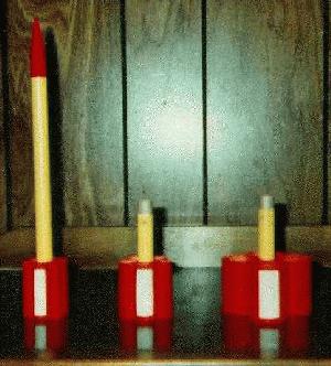
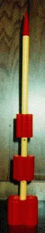
| MiniToobo
To counteract the rearward shift of the rocket's CG as stages are added, the booster stages have progressively larger tube-fins. Fortunately, tube diameters for five-tube and four-tube clusters around a BT-5 tube just happen to be close to the diameters of BT-20 and BT-55 tubes. The result is a mildly larger first booster, and a wildly larger second booster. It also works out quite nicely that by balancing the sustainer for stable flight with an A10-3T engine, the two-stage and three-stage configurations remains stable when using a 1/2A10-4T for the sustainer and A10-0T for booster(s). Stage coupling is quite solid since the top of each lower stage is squeezed between the engine and tube-fins of the adjacent upper stage. The booster's are vented a la G. Harry Stine for improved air-start reliability. I usually insert a paper liner into the boosters to reduce scorching and increase the boosters' useful lifetimes. MiniToobo is stable when flown in single-stage, two-stage, or three-stage configurations. The long profile of the sustainer combined with the compact tube-fins results in straight, high flights with little weathercocking in fairly high winds. Weathercocking becomes more noticeable as stages are added. |
|
| Specifications: Sustainer Booster 1 Booster 2 3-Stage Configuration: recommended engines: single-stage (sustainer only): multi-stage: |
Parts Lists:
Sustainer Parts List 1 - 210mm (8.25") of BT-5 body tube Booster 1 Parts List 1 - 95mm (3-3/4") of BT-5 body tube Booster 2 Parts List 1 - 95mm (3-3/4") of BT-5 body tube |
| Construction Details: Use this link for plan views of MiniToobo. They will pop up in another window. MiniToobo Plan Views NOTE: Except where noted, use yellow or white glue when glueing pieces together. |
| 1. Sustainer
Construction: 1.1 Tie one end of the Kevlar® twine to one end of the elastic shock cord. 1.2 Tie the other end of the Kevlar® twine to an EB-5 engine block. 1.3 Glue the engine block of step 1.2 into the 210mm BT-5 body tube using an exhausted mini-engine casing. Position the engine block so there is about 13mm of casing extending out of the bottom of the body tube. Withdraw the engine casing immediately. Dangle the shock cord out of the top of the tube. 1.4 Glue two 50mm BT-5 tubes together, side by side with tube ends even with one-another. Repeat with the other two pairs of 50mm tubes. Let the glue dry before proceeding to the next step. I recommend using white glue for this step, since yellow glue may deform the tubes slightly as the glue dries and shrinks. 1.5 Glue one of the tube-pairs of step 1.4 to the bottom of the 210mm tube with 13mm of the tube pair extending past the bottom of the 210mm tube. Glue another of the tube-pairs to the assembly of step 1.4, alongside and even with the attached tube-pair. Glue the third tube-pair to the assembly of step 1.4, alongside and even with the attached tube-pairs. Let the glue dry thoroughly. 1.6 Attach the streamer to the shock cord, about 180mm from the cord's free end. The streamer can be attached either by tieing the shock cord to one end of the streamer, or by taping the streamer to the shock cord with Scotch Magic Tape or a pieces of adhesive-backed paper. 1.7 Mark the 210mm BT-5 tube 88mm from the top of the tube. This mark is where the center of gravity of the sustainer should be without an installed engine. Roll up the streamer and slide the streamer and shock cord into the top of the 210mm tube. Pack a ball of modelling clay, about 6mm (1/4") in diameter, into the nose cone. Slide the nose cone into the top of the 210mm tube and try to balance the assembly on the 88mm mark. Add or remove clay to the nose cone until the rocket balances horizontally or is just slightly nose-heavy. A handy way to check balance is by tieing a string around the body tube and taping the string at the balance point. Balance can then be checked by simply dangling the rocket from the string. 1.8 With plastic cement, glue the nose cone's end cap to the base of the nose cone. Let this assembly dry. 1.9 Tie the free end of the shock cord to the nose cone end cap. |
2. Booster 1 Construction:
2.1 Make a 5mm diameter hole centered 21mm from one end of the 95mm BT-5 tube. Make another 5mm diameter hole one the opposite wall of the tube, centered 21mm from the same end of the tube. To strengthen the material around these holes, apply a coat of CA to the inside of the tube around the holes. Further instructions refer to the end closest to these holes as the "top" end. The opposite end is the "bottom" end. 2.2 Glue an engine block into the bottom of the 95mm tube using an exhausted mini-engine casing. Position the engine block so that there is 6mm of casing extending out of the bottom of the body tube. Withdraw the engine casing immediately. 2.3 Glue two 50mm BT-20 tubes together, side-by-side with the tube ends even with one-another. Repeat for another pair of BT-20 tubes. Let the glue dry completely before proceeding to the next step. I recommend using white glue for this step, since yellow glue may deform the tubes slightly as the glue dries and shrinks. 2.4 Glue a BT-20 tube-pair from step 2.3 onto the bottom of the 95mm BT-5 tube with the bottom edge of the tube pair extending 13mm from the bottom end of the 95mm tube. Before the glue has set, glue another BT-20 tube-pair to 95mm tube, alongside and even with the mounted tube-pair. Before the glue has set, glue the remaining 50mm BT-20 tube to the 95mm BT-5 tube and attached tube-pairs, with the ends of the 50mm tube even with the ends of the tube-pairs. There will be a gap between BT-20 tubes. The gap is filled by applying pressure to the cluster of BT-20 tubes squash the tubes slightly. This is done by wrapping masking tape, sticky-side outward, around the middle of the cluster while applying sufficient tension on the masking tape to close the gap between tubes, while not providing enough tension to separate the BT-20 tubes from the 95mm tube. Ensure that all of the tube pairs are even with one-another. Let the assembly dry fully. 2.5 Remove the masking tape applied in step 2.4. |
| 3. Booster 2
Construction: 3.1 Make a 5mm diameter hole centered 21mm from one end of the 95mm BT-5 tube. Make another 5mm diameter hole one the opposite wall of the tube, centered 21mm from the same end of the tube. To strengthen the material around these holes, apply a coat of CA to the inside of the tube around the holes. Further instructions refer to the end closest to these holes as the "top" end. The opposite end is referred-to as the "bottom" end. 3.2 Glue the remaining engine block into the bottom of the 95mm BT-5 tube using an exhausted mini-engine casing. Position the engine block so that there is 13mm of casing extending out of the bottom of the body tube. Withdraw the engine casing immediately. 3.3 Cut a 3mm-wide slit widthwise across the 95mm tube, 32mm from the bottom end of the tube. 3.4 If the engine clip is a fancy one with a fingertip extension, remove the extension so that the clip is simply "L"-shaped at either end. Run a 20mm-long bead of glue from the slit toward the bottom end of the 100mm tube. Insert the engine clip into the slit in the 95mm tube. Secure the engine clip to the body tube by wrapping two layers of masking tape or glued layers of a 6mm (1/4") strip of Kraft paper around the tube and engine clip. Be sure to leave 20mm of engine clip free toward the bottom end of the tube. 3.5 Glue two 50mm BT-55 tubes together, side-by-side with the tube ends even with one-another. Repeat for the other pair of BT-55 tubes. Let the glue dry completely before proceeding to the next step. 3.6 Glue a BT-55 tube-pair of step 3.5 onto the 95mm BT-5 tube, with the joint of the tube-pair centered over the engine clip and with the bottom edge of the tube pair even with the bottom of the engine clip. Before the glue has set, glue another BT-55 tube-pair to the assembly, with the ends of the tube-pairs even with one-another. Let the assembly dry fully. |
Flight Preparation Single-Stage:
Two-Stage: Wrap tape around the booster 1 engine until it fits tightly into booster 1. Insert a rolled piece of paper, with holes punched out for the booster vent holes, and slide it into the top part of booster 1. Align the vent holes of the paper insert with the booster's vent holes. This will reduce charring from the sustainer's engine. Slide booster 1 onto the sustainer's engine. The fit should be tight enough so that you can lift the rocket upside-down by the booster without the sustainer falling out. However, the fit should not be much tighter than that. The fit can be loosened by wiggling the booster around while it is coupled to the sustainer. If this doesn't help, sand the tube-fins of the sustainer where the booster body tube touches them to remove any crud and to thin the tube-fins a bit. Three-Stage: Insert a rolled piece of paper, with holes punched out for the booster vent holes, and slide it into the top part of booster 2. Align the vent holes of the paper insert with the booster's vent holes. This will reduce charring from booster 1's engine. Slide booster 2 onto booster 1's engine. The fit should be tight enough so that you can lift the rocket upside-down by booster 2 without the stages falling out. However, the fit should not be much tighter than that. The fit can be loosened by wiggling booster 2 around while it is coupled to the booster 1. If this doesn't help, sand the tube-fins of booster 1 where the booster 2 body tube touches them to remove any crud and to thin the tube-fins a bit. |
| Flight Reports: Session
1 Note: All distance are eyeball estimates I prepared the Minitoobo sustainer with a A10-3T engine. The rocket lept straight up, about 250 metres, without weathercocking noticeably. When the streamer deployed, the wind blew the rocket westward pretty quickly. The rocket and landed about 100 metres west of the launch pad with no damage. With a 30mm x 300mm crepe streamer, the rocket descended a bit too quickly and was not very visible. Next time, I'll try a 40mm x 400mm streamer. Session 2 Note: All distance are eyeball estimates I prepared all three stages for flight, with A10-0T engines in both boosters and a 1/2A3-4T in the sustainer. The rocket flew up about 60 metres, weathercocking toward the south, there was a slight pause, then booster 1 ignited and booster 2 was ejected. Booster 2 tumbled down and landed about 5 metres north of the launch pad. The booster 1 and sustainer flew up to about 250 metres, arched to the south, and dived straight down, itself in the ground 20 metres south of the launch pad. The sustainer's body tube was ripped and accordianed at the front end. However, a bit of masking tape and some smoothing of the body tube prepared the sustainer for further flights. Upon examining the engines of both boosters and the sustainer, I found that both boosters had exhausted themselves, but the sustainer's engine was not ignited by booster 1's staging charge. The sustainer engine's base was blackened, so the booster's staging charge must have activated. So, to determine whether the staging engine was a dud, I pushed the engine back into the sustainer, prepped it, and launched it. The engine ignited. The sustainer flew straight up about 90 metres, popped its streamer, and landed 25 metres east of the launch pad (the wind was shifting) with no damage. The 40mm x 400mm streamer was far more effective in slowing descent and being visible than the 30mm x 300mm streamer was. I then prepared for a two-stage flight, with an A10-0T in booster 1 and a 1/2A3-4T in the sustainer. The rocket flew straight up about 120 metres, the sustainer ignited and ejected booster 1, which tumbled to earth about 10 metres northeast of the launch pad. The sustainer flew up about 350 metres, popped its streamer, and descended to land about 30 metres east of the launch pad. This was a very pretty, impressive flight. I then prepared for a three-stage flight again, with the same configuration as the first flight of the day. The rocket flew straight up about 60 metres, then booster 1 was ignited and booster 2 was ejected. Booster 2 tumbled and landed about 5 metres northeast of the launch pad. The rocket flew up to about 190 metres when the sustainer was ignited and booster 1 was ejected. Booster 1 tumbled and landed about 20 metres east of the launchpad. The sustainer flew up out of site and was invisible until it deployed its streamer. The sustainer finally landed about 60 metres east of the launch pad. |
 |
 |