| Manufacturer: | Scratch |
M.M.X. (MicroMech-X)
All Micro-Maxx, x2 cluster,
sci-fi but not comedy, no parts from a Grissom
Design Concept
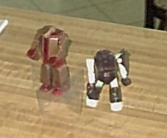
I wanted to pick a theme that I thought would be somewhat unique. I didn't think I could come up with a suitable comedy sci-fi ship that hadn't already been mentioned on r.m.r., so I looked elsewhere for inspiration. I roughly patterned this rocket after a robot model that I resurrected from the depths of our basement (a.k.a. The Rocket Dungeon). I had scoured the web, and had even thought of doing a conversion of a paper model robot, but decided to just start building and see where it went. This model started as a prototype, but as it progressed I decided to keep it as my entry.
Development Methodology
I used a tried and true procedure known as "real-time design". In this design methodology, the design is performed as you go, without the benefit of plans, diagrams, or specifications. Documentation is performed at the end, and is kept to a minimum.
Construction
I started by cutting two MMX tubes that would extend from the bottom of the robot's foot up into its body cavity. I then started at the bottom and built my way up. The plastic robot's foot was traced onto foam poster board. I cut the feet, beveled their edges, and cut holes for the MMX tubes. Next came the upper layer of the feet, followed by the front and rear leg sections. At this point, I began to think about weight, so the sides of the legs were made from card stock. The body was started with a foam board plate, with holes cut for the motor tubes. As with the leg sections, the three front and one rear section of the body are foam board and the sides are cardstock. To provide better support for the shoulders/head (i.e. the nose cone), I added a small section of BT-20 in the body cavity. A long Estes lug was inserted laterally through the BT-20 to provide an attachment point for the arms. The shoulder/head assembly started with a foam board plate. Attached to this is a sliver of BT-20 coupler and two pieces of foam board, which were trimmed to mate with the body opening. The head itself was carved/sanded from pink foam. The arms consist of two layers of foam board.
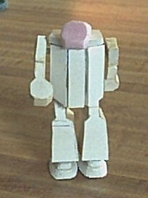
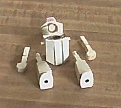
Now that the robot looked like a robot, I had to add more rocket stuff. For recovery, a piece of thin Kevlar twine was tied around the launch lug that supports the arms and was epoxied to the shoulder/head assembly. A launch lug was glued midway up the back. And finally, I scrounged some thin clear plastic for fins. The four fins were glued to the bottom of the leg above the feet.
Finishing was performed with a combination of simple water colors and some card stock cutouts. I painted the robot before permanently attaching the legs, arms, and fins so I'd have better access to its nooks and crannies.
Flight and Recovery
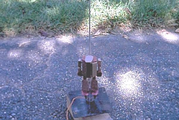
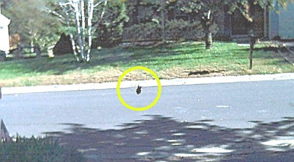
After some miscues, I finally got both motors to light. M.M.X. reached a whopping altitude of 4ft. The second photo below shows it on the way down, just before ejection.
Conclusion
Although the rocket flew, to have a mature model I'd have to build lighter. I might also opt for a lug that is closer to the axis of the motors and a different ejection method. Such conclusions are the point of a prototyping effort. I didn't find time to build V2.0, so I guess this is it for this contest.


 |
 |