| The
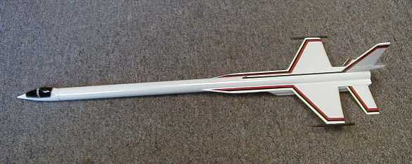
Peregrine This is a little futuristic
job I cooked up to use the nifty cockpit type nose cone I got in one of the
Estes PNC20 nose cone packs. I don't know the Estes part number, but I'm sure
you can find one at the hobby shop if you look. You could also use a plain nose
cone and build up a cockpit bulge from paper, or simply paint one on a plain
nose cone. I painted one in with gloss black and silver framing on mine.
Layout the patterns and cut them out. Use these links
to view the balsa patterns. They will pop up in another window.
Pattern
A, Pattern 1A, Pattern 2
|
Parts List:
1 - 18 in. lg. BT20/T20 Estes or Totally Tubular
1 - PNC20 as described above
1 - EB20/CR-5-20 Estes or Totally Tubular
3/32 in. balsa sheet, as required
1/16 in. balsa sheet, as required
1 - 1/4 in. square x 1 1/2 in. lg. Balsa
strip
2 - 1/8 in. dowel x 2 1/2 in. lg.
1 - 1 in. lg. 1/8 in. launch lug
1 - 1/2 in. lg. 1/8 in. launch lug
2 - 1 in. lg. 1/4 in. launch lugs
1/8 in. x 24 in. flat elastic shock cord
70 lb. Kevlar® cord approximately 20 in. lg.
1 - 12 in. diameter parachute
Snap swivel for chute if desired I used Titebond yellow wood glue throughout
construction.
|
| Round one end of the 1/4 in. square balsa and taper
the other end down to just over 3/32 in. wide on the end. This will be glued
into the notch on the rudder. Match sand
all the balsa edges. Round the edges of the stabilizers. Do not round off the
edges of the wing, front or rear extensions, rudder or the rudder
extension.
Lay out the wing pieces and glue them together as
shown on the pattern sheet. I have found that laying them flat on a sheet of
styrofoam covered in Saran wrap works well. Use straight pins to hold
everything together. (This also seems to work real well when laying out boost
glider wings using angle blocks to get the dihedral.)
Glue up the rudder in the same manner.
Glue one nacelle side plate to the bottom plate. The
side edge butts to the bottom surface of the bottom nacelle plate. Support this
on the styrofoam sheet and hold the side square with a block of wood. Glue the
other side plate on.
Glue on the side filler strips to each side. After the
nacelle sides are dry carefully sand the edges smooth. The leading and trailing
edges of the nacelle can be airfoiled or rounded as you choose. I airfoiled
mine.
Tie one end of the Kelvar to the engine block. Feed
the other end through the body tube and glue the engine block in using an old
engine casing. Position the engine block so there is 1/4 in. of casing
extending out the back. (If you have a preferred method of shock cord
attachment, by all means use it.)
After the rudder and wing assemblies are dry you can
round off the edges. Leave the root edges flat. It may be helpful to lightly
sand the root edges in case the parts did not line up perfectly.
Glue the 1/4 in. square balsa strip into the notch in
the rudder, rounded end toward the rear. This is supposed to be an ECM pod type
of thing.
Mark the rear of the body tube for 4 fins at 90
degrees. Rough up the body tube surface first. Glue on the rudder assembly with
the rear edge flush with the rear of the body tube.
After the glue has dried add root fillets. Make sure
that your guide marks go far enough along the body tube so you can get the
alignment of the rudder and wing extensions straight.
Glue the wings on and fillet as required.
|
Trim one end of each launch lug at a 45 degree angle.
Glue on the 1/2 in. LL to the bottom guide mark flush with the rear of the body
tube, with the angled end toward the rear. Align and glue the 1 in. LL with the angled end toward the
nose. The rear end of the LL should be 5 1/4 in. from the rear of the body
tube. Glue the launch lug trim pieces to each side of the launch
lugs.
The rear trim should match the end of the launch lug.
The front trim should be lined up with the rear of the lug and extend forward
of it on the exposed end.
Check fit the engine nacelle assembly to the bottom of
the model. It should contact the bottom of the wings and just touch the launch
lug trim strips. Sand to fit if required.
Glue the nacelle assembly to the bottom of the wings
with the 45 degree end toward the front of the model. I used straight pins to
keep everything aligned while the glue dried. Be careful not to split the balsa
if you do this. You could use CA to tack everything in place. I haven't had a
lot of success with using thick CA on balsa.
Once the nacelle glue has dried smooth out the edge
joints with the wing. Sand the root edges of the stabilizers at 45 degrees,
(sand each root opposite) and glue to the rear of the nacelle side 1/4 in. up
from the rear.
Glue the rudder to the nacelle on the trim piece.
Fillet the stabilizers and sand the fillet smooth on the top
surface.
Glue the 1/4 in. launch lugs into the rear corners of
the nacelle so the ends stick out just a bit, to simulate nozzles. Taper the
end of the 1/8 in. dowels and glue to the wing tips with the rear end of the
dowel extending 1/2 in. from the wing trailing edge.
Tie a loop in the free end of the Kevlar® shock cord
anchor and attach the elastic shock cord. Install the snap swivel and the chute
and youíre set for painting.
Flying the Peregrine:
I get a CG with a C6-5 at approximately 5 3/4 in. from
the rear of the body tube. This is with some rolled worms of modeling clay
stuffed into the little hole in the base of the nose cone. Add clay until your
CG is at least this far forward.
The Peregrine has successfully flown on A8-3's and
B6-4's.
|

