| Manufacturer: | Scratch |

Drake "Doc" Damerau's Descon-14 Entry
 Brief:
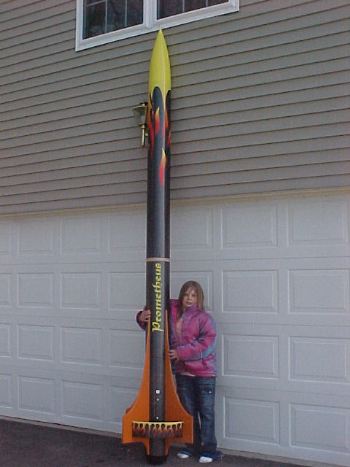
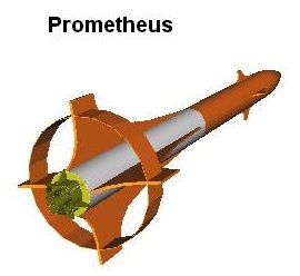
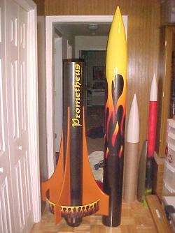
A scratch built L3 cluster rocket with a 22" diameter ring fin.
Construction:
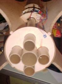
This project actually started out being my L3 project. I bought a LOC Precision Bruiser-EXP. This kit is a 7.61" diameter 9’ 4" tall rocket, and has a central 54mm MMT and two 38mm MMT’s. Not thinking (this happens with me sometimes), I wanted to build a cluster because I wanted to try my hand at air starting motors. Halfway through the build I decided to actually read the L3 certification requirements. "Clusters are specifically not allowed". Doh!
The Bruiser-EXP is a great kit, but for what I had planned, the central 54mm and two 38mm’s was not enough so I drilled for two more 38mm MMTs in the centering rings. I also added two additional ½" centering rings to round out the propulsion mount. Hey 9’ 4" tall won't do either! I added another 30" LOC section and a LOC altimeter bay to make it over 12 feet tall. Now were talking rockets here!
Fins
 With most of the components in
hand, I needed to design a rocket. A basic 3 fin design just doesn’t do
anything for me. I went with ½" aircraft plywood for the fins because
I hate doing fiberglass, and it’s right there at Lowe’s. Yeah,
It’s heavy, but I had 5mmt’s. I played with Rocksim to come up with a
fin pattern. I ended up with a swept back design to keep it interesting. I
freehand sketched the first fin and cut it out with a jigsaw. I then used that
as a pattern for the 3 remaining fins. A belt sander quickly smoothed out the
edges and air foiled them. I then added slots in the fins for the five
centering rings.
With most of the components in
hand, I needed to design a rocket. A basic 3 fin design just doesn’t do
anything for me. I went with ½" aircraft plywood for the fins because
I hate doing fiberglass, and it’s right there at Lowe’s. Yeah,
It’s heavy, but I had 5mmt’s. I played with Rocksim to come up with a
fin pattern. I ended up with a swept back design to keep it interesting. I
freehand sketched the first fin and cut it out with a jigsaw. I then used that
as a pattern for the 3 remaining fins. A belt sander quickly smoothed out the
edges and air foiled them. I then added slots in the fins for the five
centering rings.
The fins were done, but I was not yet satisfied. A ring fin! A giant ring fin! Yeah, that’s the ticket. I grabbed a 22" fiber-drum from work. You know, those 55 gallon cardboard drums that powders are shipped in? Using a series of marks measured from the top , I drew two lines around the drum 5" apart. I then cut out the big ring with a jigsaw. The edges were rough and frayed so I trimmed them a little with a hobby knife and soaked them with epoxy. Once the epoxy was hard, a palm sander made quick work of squaring up the edges. I cut slots in the fins with a jig saw so I could mount the ring fin to the main fins once they were on.
 Fin Can
The fin-can assembly went together in short order. I tacked the centering rings to all the motor mount tubes at the same time using thick cyanoacralate. This ensured proper alignment of everything. West systems epoxy was then applied to all joints. Once hardened, the fins were slipped into place and more epoxy was applied. I drilled and mounted two 5/16 eye-bolts for recovery. (not that I had a clue as to how recovery would happen at this point)
Air-Start
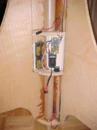
Once the fin can was complete I installed the Air-start board, wires and 3 battery holders to it. The air-start board for Transolve altimeter has provisions for an optional battery just to power the board, rather than drawing from the battery in the altimeter. I went with it having it’s own battery. It also comes with an optional relay that can be used for the igniters. Because I will be lighting as many as 4 igniters, I went with the relay and 2 batteries wired in series. The board has contacts for "safe / arm" so I used a 1/8’ phono plug and attached a big "Remove Before Flight" flag I picked up from Aerocon. I then slid the slotted airframe over the assembly and measured to cut a hatch for the air-start assembly. I cut the hatch and glued the airframe over the fin can. I pealed the glassine layer off the hatch and applied several layers of epoxy to stiffen it up. The edges of the opening for the hatch were also soaked with epoxy.
 Ring Fin
I didn’t add the ring fin until after the slotted airframe was epoxyied onto place over the fin can, just to make working on the fin can easier. This took less than an hour. I just slipped it in the slots, centered it and glued it in place with epoxy. The slots were 1 ½" longer than the ring fin, so I filled in the slots behind the ring with epoxied strips of basswood. Some sanding and wood putty left not trace of the slot.
Boat tail
I started out with wanting to add fins to the MMT sticking out of the aft end. In fact, as you see in some of the pictures, I spent 4 hours measuring, cutting, shaping and gluing them in place. The completed looked rather stupid, so I tore them off. I decided to make it a boat tail design instead. I made a smaller centering ring for the aft end that was just slightly larger than the MMT tubes. At this point, the air start system was already in place so I had to extend the output contacts to the new aft centering ring. I then made a transition template using VCP and transferred it to a piece of heavy card stock. One glued in place, I lay two layers of 6 OZ fiberglass to toughen it up.
Altimeter Bay
The altimeter bay that I started with was a LOC type. I guess you could say that this was another LOC kit bash too.
Backup Electronics
I decided to add a couple of backup timers. For deployment, I added a duel event timer and for the air-start I added a single event timer. Both from Xavien. . The XSSRT-1, "Xavien Single Stage Rocket Timer". This is a 1 second to 63 seconds’ single event timer. I tested this one for future use in air starting.
I also have the XDSRT-1, "Xavien
Duel Stage
Rocket Timer" This one is a 1
second to 63 seconds’ dual event timer. I used this timer wired in as
back-up for altimeter ejection.

I used the duel event timer as a backup for deployment. The rocket went somewhat horizontal just before the four motors lit. This threw off the calculations on when to deploy the chutes. When using a timer, you have to calculate the flight based on motor burn time and assuming a straight boost. If the rocket doesn’t go straight, the events happen sooner than you calculate. Thus, the altimeter deployed the drogue and the main but the duel timer did light its ejection charges.
I used the single event timer to test its ability to light 4 Davyfire igniters. As I put the rocket together at the field, I decided not to use the timer to air-start the motors because the air-start system that was built into the rocket was mounted and wired much better. I also didn’t want to put two igniters in each motor in fear of clogging the nozzles. I wired four igniters outside the rocket and tested its ability to light four of them. Although I didn’t have them in the motors, it did light all four igniters.
 You can see my full review on these
electronics here.
You can see my full review on these
electronics here.
Finishing
OK, I’m not much of a finishing guy. Buy hey, they look good sitting on the pad! I chose Metallic Black from Rustoleum for the airframe and an orange for the fins. I didn’t just want a basic two color paint job on this because it turned out pretty cool. I went to the local "sign guy" and asked about making decals for me. We ended up design a flames thing for it. He matched the front of the flames to the color I had picked out for the nose cone and did the rest on the computer. We made giant flames for the forward section and small ones for the ring fin. A quick run through his fonts came up with a sticker for the name. He even printed a bunch of CP and CG stickers for me when I showed him what they were. The flame stickers that he came up with were difficult to apply but it came out pretty cool nonetheless.
 The First
Flight
The First
Flight
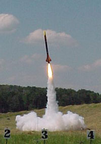
To ensure that all four motors would light quickly and at the same time, I used Davyfire igniters dipped in Igniterman pyrogen. I set her up on the away cell and wired all of the J330 igniters together. The last igniter to be installed was the one for the K1050. For this I used a homemade igniter using Igniterman pyrogen.
She lit on the second attempt. Just as it left the pad, it started to veer off course a little. By the time the K1050 burnt out, it was heading skyward at about 2,500 feet and on a 45 degree angle. I still don’t know if it weather-cocked, if the rail was too short, or if it was just underpowered.
There was a pause while it coasted. At this point I was actually saying "please don’t light, please don’t light!" …oh no…, they lit. All four J330’s snapped to life with a thunderous roar and she took off like a bat out of hell. By the time the J330’s burnt out, she was almost on her side and I’m guessing going well over 300 MPH. A few seconds later, she was completely horizontal and starting to head down. Of course the drogue deployed and the chute came out. From where I was standing, it looked like it was never attached to anything! It just virtually disintegrated when it opened.
 She fell for awhile and it was clear that
the rest of the rocket was still tethered together and the main was still in
the rocket. (Can you say: "thank God for shear pins"?) Right on cue,
the three main chutes deployed and opened up perfectly, over a mile away.
She fell for awhile and it was clear that
the rest of the rocket was still tethered together and the main was still in
the rocket. (Can you say: "thank God for shear pins"?) Right on cue,
the three main chutes deployed and opened up perfectly, over a mile away.
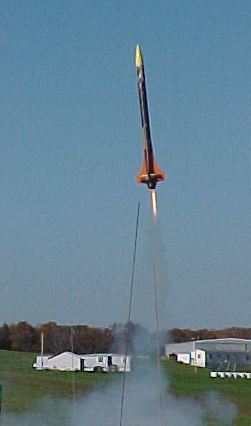
The Second Flight
The second flight was a disaster. I put a 5-grain Pro54 in the center and four 6-grain Pro38 motors in the other tubes. I set the motors to light in a different configuration this time. Because the Pro 54 didn't have as much thrust and I wanted it to leave the pad quicker, I decided to light the 54mm and two of the 38mm motors off the pad. This proved to be a bad idea. I used the igniters that came with the motors and dipped them in pyrogen, just like I did last time. Something went wrong this time because the only motor that lit was one 38mm. (you can see this in the photo.) the one motor had just enough power to get it off the pad and up about 100 feet. It came down on its tail almost vertical and fell over. Just as it fell over, the air-start board lit the other two 38's. She scooted around on the ground for about 50 feet, tearing up the side of the rocket and destroying the ring-fin. Post flight analysis showed that all igniters lit. I'll never use these motors in a cluster again! She is now in the repair shop. I think I can rebuild her but it will take months.
Sponsored Ads


 |
 |