| Manufacturer: | Scratch |
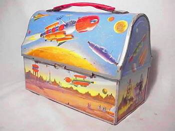 |
The Concept I have always been fascinated by 1950's era sci-fi space vehicles. The more inexplicably complex, the better. An excellent example is the lunch box I carried to school in the first grade. These dome satellite lunch boxes are relatively common and are always available on eBay. The reproduction boxes are poor quality. |
After toying with an idea for ducted ejection ala the Estes Trident for some time, I built a test vehicle in 2001. The two body tubes were connected by faucet connector hoses which ducted ejection gases from the lower motor section to the upper recovery section. The prototype used 2.6" gift wrap tubing, industrial grade toilet paper cores and corrugated cardboard centering rings. The airframe was completely fiberglassed. As it started coming together, I decided I liked it so much that I was already thinking about scaling it up. I named it the Protonator I. It has flown about 10 times on a variety of G and H impulse motors.
I started work on the Protonator II, a 1.6X upscale from the prototype less than two months after the first flight of the Protonator I. It took about 11 months to complete.
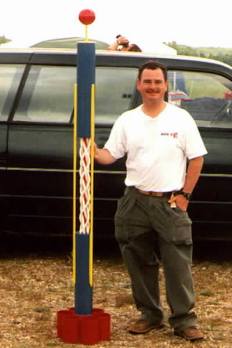
Protonator II Specifications
| Length: | 79" | ||
| Diameter : | 4.25" | ||
| Motor mount: | 38 mm X 13" | ||
| Empty weight: | 10.1 lb. | ||
| Launch weight (J350): | 11.6 lb. | ||
| Tube fin dimensions: | 4.25"D X 6"L | ||
| Number of tube fins: | 6 | ||
| Parachute: | 42" center diameter, 3 skirt Sky Dangle (Homemade Sky Angle knockoff) | ||
| Recommended motors: | J350-M | I435-M | I300-S |
| Estimated altitude: | 1800' | 1300' | 900' |
| Recommended ejection charge: | 1.5g FFFF BP | ||
Parts List
| 3 | 4.25"OD X 43" Mailing Tubes | Mail Boxes etc. Cut into one 22", one 26", six 6" and one 3" sections. |
| 3 | 1/2" X 48" Dowel Rods | Home Depot. Grind one end rounded, other end conical 'pencil point.' |
| 1 | 3/8" X 24" Dowel Rod | Home Depot. Cut into one 7" and ~eight 2" sections for Nose ball pylon and SC mount plate reinforcers. |
| 18' | Faucet connection hose - white | Home Depot. Cut into six 36" lengths. |
| 30" | Air tool hose, 1/2"D - orange | Home Depot. |
| 1 | 1/8" plywood, 10" X 25" | Hobby Shop. For CR's and bulkhead, and nose base. |
| 1 | 1/4" plywood, 5" X 5" | Hobby Shop. For SC Mount plate. |
| 13" | 38 mm ID phenolic tube | PML. Motor Mount Tube (MMT) |
| 1 | 4" Styrofoam Ball | Craft Shop. |
| 9" | Brass tubing for 1/2 Launch Rod | Home Depot. |
| 2 yd | 4 oz fiberglass cloth, 60" | Aerospace Composite Products. |
| Consumables | Epoxy, Epoxy thickener, 91% Isopropyl alcohol for thinning epoxy, lightweight spackling, finish filler. Rustoleum white primer, Rustoleum enamel: 7762 Sunrise Red, 7727 Royal Blue, Rustoleum High Performance enamel: 7543 Safety yellow, red glitter, blue glitter, Future floor polish. | |
| Hardware, heavy duty | Home Depot. Quick links, eye bolts, blind nuts, hex nuts, cap screws, 3/8" brass tube and aluminum storm window fasteners for motor retention. | |
| 25' | Tubular Nylon - 1" | Hobby vendor. For shock cord (SC). |
| 5' | 1/2" Nylon web | Para Gear - Skokie IL. For nose "cone" tether (also great for parachute shroud lines). |
| Polyester Thread | To sew SC and parachute | |
| 1 | Parachute, for 11 lb. rocket | I built my own from rip stop nylon and 1/2" nylon web patterned after a three skirt Sky Angle chute. |
| 1 yd | Nomex | McMaster-Carr. SC and chute protector (I sew my own) |
Preflight Testing
Two tests of the ejection system were made; one with 1g FFFF BP and one with 1.5g. Both were successful but the 1.5g test seemed more certain.
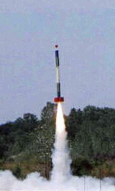
First Flight
The first flight was made on 8/11/02 at a Tripoli Wisconsin Association Launch at Bong Recreation Area west of Kenosha, Wisconsin. The flight was powered by an Aerotech J350-M (manufactured pre-fire) and used 1.5g BP. Winds were light. The rocket performed flawlessly and was recovered with no damage.
Construction Details
![]()
![]()
![]()
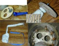
 Motor Mount
The Motor Mount is relatively conventional with three centering rings and T nuts to accommodate motor retention hardware. The one unconventional feature is the ejection charge deflector which is made from a plywood disc and nylon web which has been stiffened and coated with epoxy. It is mounted into the Power Section by gluing the forward CR while dry fitting the aft CR for alignment only. The aft CR is removed and the forward CR is filleted from both sides. The middle and aft CRs are then positioned and glued sequentially to both the MMT and the Power Section..
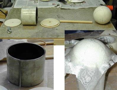 Nose Ball Assembly
A segment of a three inch section of BT is removed to allow it to be inserted inside a BT section. Note cards and plastic food wrap are used to provide some slack in the fit and prevent bonding. A piece of fiberglass is laid up on the inside of the split ring and allowed to cure. The split ring is then removed from the BT section. Two bulkheads are cut from 1/8" ply to fit snugly inside the split ring. Using them to force the ring into a round cylinder, the outside of the ring is fiberglassed. The two bulkheads are removed.
A third bulkhead is cut to the outside diameter of the BT (i.e. 4.25") plus a little extra to allow sanding to the precise final diameter. This bulkhead is glued concentric to one of the smaller bulkheads. A hole is drilled through these to fit the 3/8" Ball Pylon (dowel rod )
The Styrofoam ball surface is filled with lightweight spackling and sanded several times until smooth. The ball is then fiberglassed in sections using satin weave cloth. Further filling and sanding are followed with a coating of epoxy. A 3/8: hole is drilled true into the ball for the Pylon.
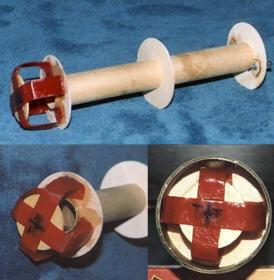
Ejection Ducting
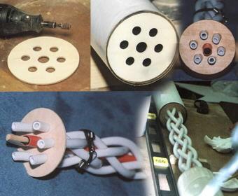 Two bulkheads are cut and holes are drilled as shown to accommodate the central compressor hose and
surrounding faucet connection hoses. The hose ends are roughened (to provide better bonding later) and inserted
into one of the bulkheads. A dowel rod may be inserted into the Central hose to provide rigidity during
assembly. The outer tubes are then woven around the central hose and inserted into the second bulkhead.
Length is adjusted to ~22 inches (bulkhead to bulkhead), excess hose cut off, ends roughened and both bulkheads are
bonded to the hoses with epoxy. After the epoxy cures, the bulkheads are carefully glued into the Recovery and
Power Sections with ~0.25 inch recess.
Two bulkheads are cut and holes are drilled as shown to accommodate the central compressor hose and
surrounding faucet connection hoses. The hose ends are roughened (to provide better bonding later) and inserted
into one of the bulkheads. A dowel rod may be inserted into the Central hose to provide rigidity during
assembly. The outer tubes are then woven around the central hose and inserted into the second bulkhead.
Length is adjusted to ~22 inches (bulkhead to bulkhead), excess hose cut off, ends roughened and both bulkheads are
bonded to the hoses with epoxy. After the epoxy cures, the bulkheads are carefully glued into the Recovery and
Power Sections with ~0.25 inch recess.
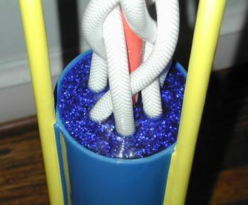 As a final touch, the recess was filled with tinted, glittering epoxy. Blue glitter was washed with
a 91% alcohol to remove the blue tint. A small volume of alcohol and a large amount of glitter produces the darkest
tinting of the alcohol. The alcohol was decanted from the glitter and added to a batch of mixed epoxy.
Fresh blue glitter was used to cover the bottom of the aft recess (in the Power Section) and the tinted epoxy was
carefully poured over it. Floating glitter was sunk with a pinpoint and the recess was uniformly filled to the
brim by adding tinted epoxy drop wise with a disposable plastic dropper. After curing, the same treatment was
applied to the forward recess in the Recovery Section using red glitter. A similar treatment was applied to the
inner recess of the Nose Ball base.
As a final touch, the recess was filled with tinted, glittering epoxy. Blue glitter was washed with
a 91% alcohol to remove the blue tint. A small volume of alcohol and a large amount of glitter produces the darkest
tinting of the alcohol. The alcohol was decanted from the glitter and added to a batch of mixed epoxy.
Fresh blue glitter was used to cover the bottom of the aft recess (in the Power Section) and the tinted epoxy was
carefully poured over it. Floating glitter was sunk with a pinpoint and the recess was uniformly filled to the
brim by adding tinted epoxy drop wise with a disposable plastic dropper. After curing, the same treatment was
applied to the forward recess in the Recovery Section using red glitter. A similar treatment was applied to the
inner recess of the Nose Ball base.
![]()
![]()
![]()
Tubes
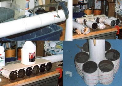
The inside of the mailing tubes are washed with a solution of mixed epoxy and 91% isopropyl alcohol (~2:1 by
volume). The caps that come with the tubes do a good job of keeping the solution inside while you shake it around
to ensure that all surfaces are covered. The excess solution is poured out and can be used to coat another
tube. Start with lots of epoxy and don't be afraid to add more alcohol to keep the viscosity down.
The outside of the tube is lightly sanded to remove the gloss, then cut to lengths and fiberglassed. The tube fins are first siamesed, then attached together as a ring around the Power Section (but not bonded to the Power Section at this time.) The ring of tubes is then removed from the Power Section and thoroughly filleted and fiberglassed together. The ring can then later be bonded to the Power Section aligned to the struts with approximately one inch rearward offset to allow the model to stand upright with a motor loaded. A brass or copper launch lug is positioned into one of the triangular gaps and fillets, foam and filler are used to fill the gaps.
Structure
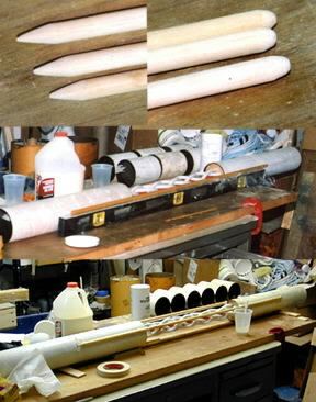 Struts are made from 0.5 inch dowels. Forward ends are blunted and aft ends sharpened as shown.
The Struts are carefully positioned around the body sections with approximately 13 inches of attachment to each
section. A perfectly flat work surface is essential for this step. Deep fillets are applied with thickened
epoxy. Two layers of fiberglass are applied across each attachment and the unattached section of each strut is
wrapped with two layers of fiberglass.
Struts are made from 0.5 inch dowels. Forward ends are blunted and aft ends sharpened as shown.
The Struts are carefully positioned around the body sections with approximately 13 inches of attachment to each
section. A perfectly flat work surface is essential for this step. Deep fillets are applied with thickened
epoxy. Two layers of fiberglass are applied across each attachment and the unattached section of each strut is
wrapped with two layers of fiberglass.
Two extra layers of fiberglass are applied to the forward end of the Recovery section to reduce the chance of zippering.
Recovery
A 0.25" bulkhead is bored out for two 1.25" gas vents and a heavy duty eye bolt as shown. A shock cord (SC) is attached to the eyebolt by sewing and covered with a Nomex sheath attached to a chute protector. the eye bolt is secured to the bulkhead with epoxy-locked washers and nuts. The bulkhead is glued into the Recovery Section and reinforced with ~eight dowel pieces and lots of thickened epoxy. A longer SC is attached to the mounted SC with a heavy duty quick link.
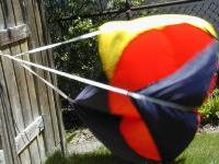
This is the Sky Dangle parachute I made for the Protonator II.
 |
 |