| Manufacturer: | Scratch |
![]()
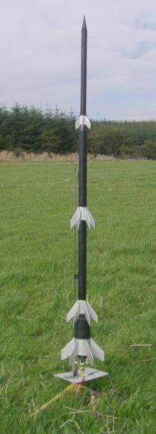
Adrian Hurt's Descon-14 Entry
Rheinbote was a WW2 German missile, not as famous or destructive as the V-2, but interesting in that it was a four stage rocket. About 220 were fired at Antwerp in 1944, probably not doing much damage as the warhead only had 20kg of explosive. (Sometimes the upper stage was not separated, to increase the impact weight.) It had a maximum range of about 200km and an apogee of about 70km.
I first got interested in Rheinbote as a result of a thread on the newsgroup rec.models.rockets concerning the V-3. This was not a rocket, but a big gun. While searching for a website to show as evidence, I found Bert Hartmann's "Luftarchiv" site (now to be found at http://www.luftarchiv.de/). As well as enough photos to prove the point even to anyone who can't read German, this site also has pages about things which were rockets, including Rheinbote. My first reaction when I saw the photos of Rheinbote was "it's long, it's thin, it's got decent fins; someone could probably make a flying model of that". Then I read the specifications - four stages, six engines in the first - and thought "I'm going to make a model of that"!
The diameters of the real rocket's stages were 535mm (1), 268mm (2 and 3), 190mm (4). The proportions of these aren't far off the proportions of the diameters of Estes BT-80, BT-55 and BT-50. Stage 1 has six 18mm motor mounts, with the nozzles angled outwards, partly for realism and partly to angle the thrust towards the CG to reduce instability if one failed to ignite. The other stages each have one 18mm motor mount.
For venting, there are small holes in the top of stage 1. Half the motor mount ejects from the rear along with a small parachute. The other three motor tubes are separated by partitions so that if one motor fails to ignite, the others don't ignite it from the front when they burn out. Stages 2 and 3 have their motor mounts held in place, not by the usual centering rings, but by strips of balsa with thickness equal to the difference between the outer radius of the motor mount and the inner radius of the body tube. The gap between the motor mount and body tube thus becomes a vent which is not visible when the rocket is assembled. Stages 2 and 3 are recovered by tumbling, with small Nomex streamers to destabilize them so they don't lawn-dart. Stage 4 is recovered with a conventional streamer.
Ignition is by Quickmatch fuse. This allows the six motors of stage 1 to be lit reliably from a single igniter, and allows stages 2, 3 and 4 to ignite even though stages 2 and 3 are too long for normal vented gap staging. (If you have a controller with enough power, you may prefer to use separate igniters for the stage 1's six motors.)
![]()
![]()
Required materials: BT-80, BT-55, BT-20, 1/8" thick balsa, cardboard, heavy paper, spent 18mm motors, kevlar shock cord, dowel, 5mm launch lug
Cut 152mm of BT-80 to make the body tube. Mark alignment lines for six fins and a launch lug. Glue the launch lug in place 67mm from the rear end. Make the fins from 1/8" balsa using the template.
Cut 70mm of BT-20 to make a motor mount. Cut 5mm off the front end of a spent 18mm motor to make a thrust ring. Glue the thrust ring into one end of the motor mount. Repeat this procedure five more times.
Make a cardboard centering ring to accommodate the six motor mounts inside a BT-80. Draw a circle 65mm diameter using compasses. Use a protractor to mark six points at 60 degree intervals, then draw three lines across the circle through the center and opposed pairs of points to divide the circle into six. Draw another circle 45mm diameter. At each point where this circle intersects one of the lines, draw a circle 20mm diameter. Depending on the thickness of cardboard you are using, you may wish to make two such rings and glue them together for strength.
Make a second centering the same way, but instead of 45mm, make the inner circle 40mm diameter. This will mean that, when the motor mounts are in place, they will be angled inwards, so that if one of the motors fails to ignite, the rocket will be less likely to be pushed off course.
You may, of course, prefer to use the computer program of your choice to draw templates for the centering rings!
Glue the motor mounts into the centering rings. It may be useful to mark a line along each mount tube which can then be aligned with the lines on the centering rings. The first centering ring should be 40mm from the rear of each motor mount tube; the second centering ring should be right at the front end.
Now cut the entire motor mount in half vertically, so that three motor mounts are in each half. Some slight damage to the front ends of the motor mount tubes is inevitable, but does not matter because that end is well reinforced by the thrust rings.
One half will be fixed into the booster; the other half will eject during flight. Decide which half will be fixed. Cut a rectangle of cardboard to fill the gap between the centering rings of the fixed half. Glue the half motor mount into the rear of the body tube so that the rear half ring is flush with the aft end of the body. Cut a 20mm length of BT-80, cut it in half lengthwise, glue one half inside the other and trim the ends to make a double thickness half tube. Glue this into the body so that it is just past the forward half ring of the fixed motor mount. This forms a thrust block for the ejecting motor mount to push against.
Bore a small hole in the forward centering half ring of the ejecting motor mount, pass the kevlar cord through the hole, then tie the cord to one of the motor tubes. Seal the hole with glue. Ensure that the ejecting mount will slide in and out of the booster; if necessary, sand the centering half rings lightly.
 To make the coupler from 1st to 2nd stage,
cut a piece of BT-55 50mm long. Decide which end will be the front and mark it
18mm from that end. Make two centering rings to fit BT-55 inside BT-80. Glue one
at the 18mm mark and one at the rear end. Bore two small holes in the forward
ring, close together; and one larger hole in the aft ring directly below them.
To make the coupler from 1st to 2nd stage,
cut a piece of BT-55 50mm long. Decide which end will be the front and mark it
18mm from that end. Make two centering rings to fit BT-55 inside BT-80. Glue one
at the 18mm mark and one at the rear end. Bore two small holes in the forward
ring, close together; and one larger hole in the aft ring directly below them.
Make a tube by rolling and gluing heavy paper, 45mm long and wide enough that it will fit easily over a BT-20. Make two centering rings to fit this tube inside BT-55. Glue one at each end of the tube. Glue this assembly into the BT-55 so that one centering ring is flush with the rear end.
Cut a piece of BT-55 35mm long. Slit it lengthwise, roll and glue it so that it will just fit inside a normal BT-55, then glue it into the front end of the coupler so that it sits on the forward inner centering ring.
The 1st stage booster is partitioned so that, if one motor fails to ignite, it will not be ignited from the front by the others when they burn out. There is also a large partition to seal off the ejecting mount. The large partition is approximately a half ellipse 65mm wide and 90mm long. Dry fit it into the body so that the base lies along the edge of the fixed motor mount; trim the sides so that it will fit past the thrust block. Try to fit the coupler into the top of the body. Trim the top of the partition until the coupler fits in with the aft centering ring touching the top of the partition. Make two partitions to form a duct from the middle tube of the fixed motor mount to the coupler, blocking off the other two tubes. (I didn't actually measure this bit - I just cut a piece of cardboard about the right shape and size, trimmed it to fit, then sealed the edges with glue!) Glue the partitions in place. Seal the joints with glue fillets.
Pass the shock cord through the body from the rear. Bore a hole in the coupler's aft centering ring and bring the shock cord through. Tie the shock cord to a short piece of dowel. Glue the dowel to the centering ring. Once it is dry and secure, glue the coupler assembly into body tube so that the forward centering ring is flush with the front end.
![]()
Required materials: BT-55, BT-20, 1/8" thick balsa, 3/32" thick balsa, cardboard, heavy paper, spent 18mm motor, kevlar shock cord, Nomex, 5mm launch lug
Cut 384mm of BT-55 to make the body tube. Mark alignment lines for six fins and a launch lug. Cut a balsa rectangle 18mm square to make a stand-off. Cut 20mm of launch lug and glue it to the stand-off. Glue the stand-off to the body tube, 140mm from the rear end. Make the fins from 3/32" balsa using the template.
Cut 140mm of BT-20 to make the motor mount. Remove the clay nozzle from the spent 18mm motor, then glue it into the front end of the tube so that the front end of the spent motor is 5mm inside the tube. Cut four strips of 1/8" balsa 70mm x 13.9mm (the thickness is the difference between BT-55 inner and BT-20 outer diameters). Glue these at equal intervals around the motor tube, aligned lengthwise, one end level with the top of the tube. These will support the motor tube instead of centering rings, making the rear end of the booster into a vent to prevent premature separation of the next stage. You may wish to paint the motor tube now to make it look like the exhaust nozzle. Glue the motor mount into the rear of the body so that the tube extends past the rear of the body by 40mm, i.e. there should be 30mm clear inside the body before the balsa supports.
Roll and glue a tube of heavy paper, of sufficient diameter to slide easily over the motor tube, 60mm long. Make four centering rings to fit this tube, outer diameter 31.5mm. Glue one ring level with the forward end of the tube, and one ring each at 2mm, 28mm, and 32mm from the forward end. Cut two strips of heavy paper, 2mm x 99mm and 4mm x 99mm, and wrap these round the forward and middle pairs of centering rings respectively. The whole assembly should slide easily in and out of a BT-55. Cut one more centering ring, outer diameter 32.5mm, and glue this level with the rear of the tube. Then glue the whole assembly into the forward end of the body so that 30mm protrudes from the front; this should include the forward ring and half the middle ring. This is the coupler to Stage 3. Cut a strip of Nomex 300mm x 25mm and tie it to the coupler using the kevlar shock cord.
Test fit Stage 2 onto Stage 1's coupler. Ensure that the fins and launch lugs on each stage line up. (Alignment of the fins from Stage 1 to Stage 2 is not essential for a safe flight; alignment of the launch lugs is!) Stage 1's coupler should hold Stage 2 in line, should not allow it to wobble significantly, and should allow it to detach easily. It should be able to fit entirely into Stage 2 without being blocked by the motor mount supports.
![]()
Required materials: BT-55, BT-20, 1/8" thick balsa, 3/32" thick balsa, cardboard, heavy paper, spent 18mm motor, kevlar shock cord, Nomex, 3mm launch lug (optional)
Cut 359mm of BT-55 to make the body tube. Mark alignment lines for six fins. Make the fins from 3/32" balsa using the template.
Optional: you may wish to fly the upper two stages by themselves. It's cheaper and easier than flying the whole rocket! If so, fit two 3mm launch lug to this stage, 160mm and 280mm from the rear end respectively.
Make and fit a motor mount the same way you did for Stage 2.
Roll and glue a tube of heavy paper, of sufficient diameter to slide easily over the motor tube, 70mm long. Make four centering rings to fit this tube, outer diameter 23.5mm. Glue two rings together level with the forward end of the tube and two more 25mm from the forward end, forming double thickness rings. The whole assembly should slide easily in and out of a BT-50. Cut three more centering rings, outer diameter 32.5mm; glue two together 20mm from the rear end and one level with the rear end. Then glue the whole assembly into the forward end of the body so one of the two 32.5mm rings forming the double thickness ring is just visible. Make a conical transition to cover the gap between the front of the body tube and the aft double thickness 23.5mm ring. (This can be made from a ring of heavy paper, inner radius 43.6mm, outer radius 69.3mm.)
This is the coupler to Stage 4. Cut a strip of Nomex 140mm x 18mm and tie it to the coupler using the kevlar shock cord. (This is too small to be a proper streamer, but it will destabilize the booster and prevent it from lawn-darting! Anything larger may not fit easily into the space between the coupler and Stage 4's body tube.)
Test fit Stage 3 onto Stage 2's coupler. Roll Stage 2's Nomex streamer round the coupler, then check that Stage 3 will fit easily onto the coupler.
![]()
Required materials: BT-50, BT-20, 3/32" thick balsa, cardboard, heavy paper, 2 x spent 18mm motor, elastic shock cord, clay
Cut 379mm of BT-55 to make the body tube. Mark alignment lines for six fins. Make the fins from 3/32" balsa using the template. (You may wish to fit a launch lug to stage 4 to fly it alone; I didn't.)
Cut 115mm of BT-20 to make the motor mount. Cut one spent 18mm motor in half to make a thrust block. Glue the thrust block into the front of the motor tube so that, when the second spent motor is inserted into the rear of the tube, it will touch the block with about 5mm sticking out of the tube. Make two centering rings to center BT-20 in BT-50. Glue one near the front end of the motor tube, and the other 66mm from the rear end. You may wish to paint the motor tube now to make it look like the exhaust nozzle. Glue the motor mount into the rear of the body so that the tube extends past the rear of the body by 40mm, i.e. there should be 25mm clear inside the body before the aft centering ring.
The nose cone can be rolled from a 75mm radius circle cut from heavy paper. Also roll a hollow cylinder, 24mm diameter, 24mm length, to form the nose cone's shoulder. Glue this into the nose cone base. Attach the shock cord both to the body tube and the inside of the nose cone shoulder using standard Estes-style folded paper mounts. Then stuff the nose cone solid with clay. (It needs to be heavy for the rocket to be stable with all those fins, especially when when only stages 2, 3 and 4 are present.)
Roll Stage 3's Nomex streamer round its coupler, then check that Stage 4 will fit easily onto the coupler without significant wobble.
And now you can assemble all four stages into the completed rocket.
![]()
The photos I've seen of Rheinbote in actual service are black and white, so I can only guess what colour the rockets may have been - possibly green or grey. But I've seen colour photos of a specimen at RAF Museum Cosford, which show black body and silver fins. I like a combination of black and silver, so that's the scheme I used! (More recently, I've seen some more photos which indicate that the nose cone and about 26mm of Stage 4's body tube should be silver. The colour scheme for my replacement Stage 4 is altered accordingly.)
![]()
At a small club flying session, I tried launching stages 3 and 4 alone as a two-stage rocket.
Stage 3: B6-0
Stage 4: B6-6
The Quickmatch wasn't very quick, so there was a delay between stage 3 burnout and stage 4 ignition which caused the rocket to weathercock before separation. Stage 3 landed in the field; stage 4 landed in a tree, but not high up, and was recovered.
Rheinbote went to International Rocket Week 2003. And on 23rd August, it went to the HPR field for its full stack flight.
Stage 1: 3 x C6-0, 3 x C6-3
Stage 2: C6-0
Stage 3: C6-0
Stage 4: C6-7
The stage 1 motors were lit by Quickmatch, and all ignited. Six C6's together make a very pleasant sound! Stage 1's parachute separated, so it lost a fin when it landed. All other stages ignited successfully via Quickmatch. Stages 2 and 3 were recovered intact. Stage 4 went a long way up, drifted a long way away, and was lost. But that was to be expected, and anyway, it's the simplest part to rebuild...
![]()
Fin templates with 50mm x 10mm scale
 VCP
diagram
VCP
diagram


 |
 |