Scratch SA-2 Guideline Original Design / Scratch Built
Scratch - SA-2 Guideline {Scratch}
Contributed by Niall Oswald
SA-2 Guideline SAM
By Naill Oswald
Brief
A 2-stage sport scale model of the ubiquitous SA-2 ‘Guideline' Surface to Air missile, designed to fly on 24mm BP motors.
Introduction
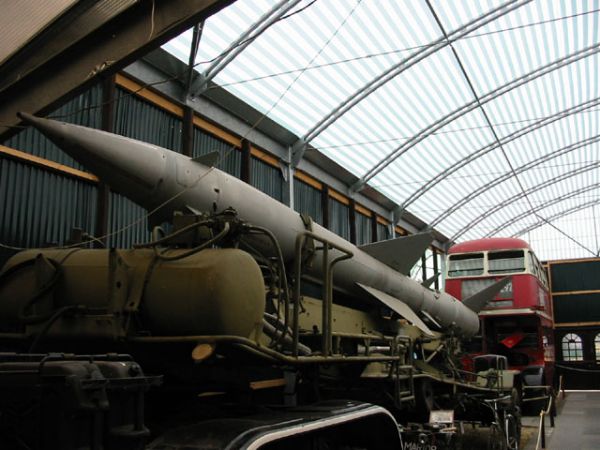
Shortly after I became interested in rocketry, I paid a visit to a local transport museum, and among the exhibits was an SA-2 SAM and its associated transporter. The SA-2 is pretty much the archetypal SAM – for good reason since something like 10,000 have been launched in active service. I think it is a nicely proportioned missile, with large rear fins and a sleek profile, and looking at the real thing, I thought to myself ‘that would be good to model'.
Some time later I found a scale drawing by Peter Always of the SA-2, and had a look at the ratios of diameters of the booster and sustainer. The booster is 65 cm in diameter, and the sustainer is 50 cm. This works out quite nicely for either 2” and 2.5” tube, or for BT-55 (33.7mm) and BT-60 (41.6mm) (0.8 vs 0.77). I decided to go for this, since it would work nicely for Estes C11 and D12 motors.
The first step was to finalize the scale factor, and work out the dimensions of the various parts of the rockets. Its been a while since I did all the sums, but my aim was a good overall model, rather than super-accurate scale detail. As such I looked to use off-the-shelf parts as far as possible, but I found that the Estes PNC-55AC (Bullpup) and TA55-60 transition were good matches for the SA-2 NC and transition section.
My scale factor worked out to approximately 1:15, its not exact but its close enough. I scaled all the lengths by this factor to give me the fin dimensions and the lengths of the body tubes.
Design
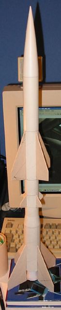
The body tubes are fairly straightforward – there is a 326mm length of BT-55 which forms the sustainer body and an 132mm length of BT-60 which forms the booster body. Including the nose cone an fins the overall length is 671mm. The SA-2 has 4 sets of 4 fins, but I only modeled three, missing the small forward fins attached to the NC. This was more due to forgetting to do them than anything else, there's no reason why a future build couldn't include them.
The sustainer has a large set of fins roughly in the middle of the BT, and smaller set aft of those. The booster has large fins which extend beyond the rear of the body tube. The SA-2 booster also has a large nozzle which extends as far as the booster fins.
I built up a full model of the rocket using SpaceCad3 (demo version), which was also used to determine that 75g of noseweight would be needed to make the rocket stable in 2-stage configuration with 2 D12's.
Parts List
- Xxxmm BT-55 (I used Apollo 11/Totally Tubular tubing)
- Xxxmm BT-60
- ACR-5060 fibre centering rings (3)
- ACR-2060 fibre centering rings (2)
- ACR-5055 kraft centering rings (3)
- AEB-50HD 24mm motor blocks (2)
- Xx mm AET-50mf 24mm foil lined motor tube (2)
- Xxmm BT-20
- Estes PNC-55AC ogive plastic NC
- Estes TA-5560 plastic transition
- 1/8” Balsa sheet for fins
- 3 and 5 mm launch lugs
- Kevlar cord, nomex square, elastic and parachute for recovery
- Paper for ‘nozzle' shroud
- Small woodscrew or self-tapping screw
Construction
Overall, construction is reasonably simple, and uses standard model techniques and materials. The sustainer motor mount is a little unconventional, and the booster uses an internal stuffer tube, as well as the ‘nozzle', so there is a little more to construction than the usual 3/4FNC type models. There are also 12 fins to cut, sand and finish, so a bit more work is involved in that respect.
The first step is to assemble all the parts, and to cut out and round the edges of the fins, ready for bonding to the body tubes. The body tubes and motor mounts also need to be cut to length before proceeding. I would suggest also marking both body tubes for 4 fins at this point.
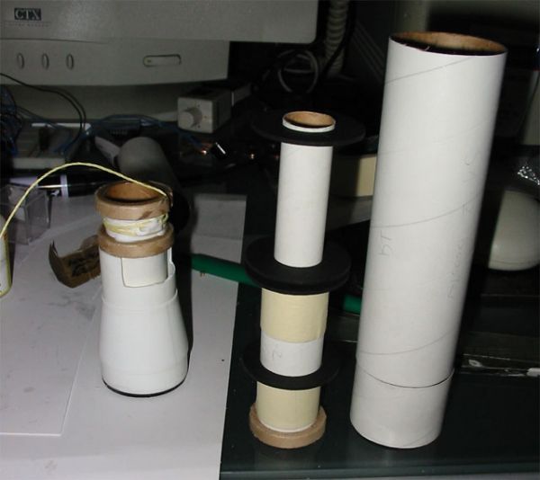
With the booster tube cut, I assembled the booster MMT assembly. This consists of a motor tube long enough to form the booster ‘nozzle' and give a useful length for centering in the BT, and two centering rings. One centering ring is bonded at the top of the MMT, and the other where the BT ends and the MMT extends beyond it. One of the 5055 rings is bonded to the end of the MMT, as part of forming the nozzle. Using the –mf tube, I had to sand the fibre rings and peel a wrap of paper from the kraft rings to fit the thicker tubing. In the usual way, a motor block was also bonded into the booster MMT at the appropriate place to fit a 24x70mm motor.
My intention when building was to use quickmatch for reliable staging, so I set up a stuffer tube in the booster to keep the hot gases and particles away from the main BT wall. This consists of a length of BT-20, which fits into the motor block and is centered in the tube with a pair of 2050 fibre rings. This runs to approximately 25mm short of the front of the booster BT and is all bonded with 5 minute epoxy.
The nozzle is formed by rolling an appropriately sized cone from paper, cutting off the tip, and using PVA glue to bond it to the MMT which extends from the booster stage. With the MMT and nozzle assembled, the booster fins can be attached – I used CA to do this, but as with all models, personal preference may be different. At this point all the booster needs is launch lugs, and I installed mine in the ‘fin root' position, which I quite like. I put 3mm and 5mm lugs on opposite sides of the body tube to allow use of a stronger ‘maxi' rod where available. I realized at this point that the rocket would only be able to fly easily with both stages attached, so I made another stuffer tube to allow the booster to carry a motor with an ejection charge, and eject up through the stuffer tube into the sustainer. This prevents the sustainer MMT getting filled with ejection gunk, and keeps the gases from blowing the sustainer and booster apart at ejection. I also added a small woodscrew to hold the stages together for single stage flight, but I think plastic rivets would be a better idea.
 Moving on to the sustainer, the construction is pretty much straightforward apart from the motor mount. The motor is mounted inside the transition, so the sustainer is male and the booster is female (rather than the usual arrangement with a coupler on the booster.
I carefully modified the transition to allow the motor mount to be installed inside it. This involved removing the front and rear sections of the transition, including the shock cord attachment points, and modifying the appropriate centering rings to fit inside the transition. The rear CR is a 5060 ring which has been sanded down, and the forward rings are 5055 kraft rings. I used two, but I think one would suffice. At this stage a Kevlar leader can also be attached to the MMT assembly, which I bonded with a mixture of PVA and 5-minute epoxy (not literally a mixture, but different parts were bonded with different adhesives).
The next step is to install the sustainer fins, which is easier if done before installing the completed motor mount. The front of the forward fins should be located xx mm from the top of the BT and the rear of the rear fins should be located xx mm from the rear of the body tube. With the fins bonded, the motor mount can be bonded inside the tube, making sure the Kevlar leader is fed through the tube first.
The NC can then be weighted – I used panel pins and epoxy to add 75g to the NC, but ‘rocket caviar' would do just as well (lead shot and epoxy). The elastic shock cord can be attached to the Kevlar leader (I used a keyring as the attachment point between the two) and a nomex square slipped onto the elastic before attaching it to the nose cone.
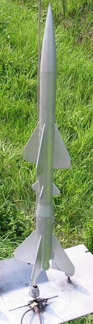
After this, the rocket needs to be finished. I painted mine in a hurry, and in late October in an unheated garage I had real problems with the silver spray paint I used. After a couple of coats of primer, I sprayed on the silver, and it wrinkled up quite badly. In the end I think I ended up sanding off the wrinkles and giving it a light spray over, but the finish job really could be a lot better. As it is, the rocket (I think anyway) has a look of bare metal that's been exposed to the elements a bit, so in keeping with its military theme! If I was building the rocket again I would put proper fillets on the fins, use sanding sealer on the fins, and properly fill and prime the body tubes.
With the various places the SA-2 was used in, there are undoubtedly many colour schemes, mine was just simple and reasonably suitable for the rocket.
Flight Reports
The first flight of the rocket came a long time after I built it, at Big EARS 2003. Given that I had the rocket ready in November 2003, it was a little slow flying it for the first time in May 2004!
I loaded up the booster MMT with a D12-3, and installed the stuffer tube by pushing it into the motor block of the upper stage MMT and taping it up, to keep the MMT from getting filled with ejection residue. The upper stage was prepped for recovery as usual – I think I had an Estes 24” or 18” chute installed at this time.
The flight was nominal, with ejection slightly on the early side. Not a great altitude with a single D12, but not a problem for recovery. The descent was slow on the big chute, which was quite tricky to fit in the BT-55 sustainer. No damage was sustained, a good first flight.
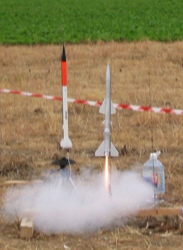
For the second flight, I decided to fly with a D12-0 in the booster and a C11-5 in the sustainer. I installed a length of quickmatch into the nozzle of the sustainer motor, and trimmed it so that the exposed ends of the internal fuses would be in contact with the exposed propellant of the booster motor. The rocket took off as before, and staged perfectly. The added quickmatch made staging a bit more dramatic than usual, and the top stage coasted to an apogee ejection after the short burn of the C11. The booster tumbled in (large fins) and suffered no damage. The sustainer also recovered without problems, and landed a short way out in the field.


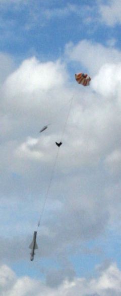
The third flight of the SA-2 came at UKRA 2004, and was on the ‘full-up' configuration of D12-0 to D12-5. Again the sustainer motor had quickmatch installed and sized to meet the booster propellant. On prepping the recovery system, I though the shock cord looked a little crispy, but went ahead without replacing it.
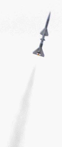
The flight was good, with staging working perfectly, with quite a whoosh, and the rocket gaining a good altitude. However at ejection, the nosecone separated, and the sustainer came in without a parachute. Oddly, it came in backwards (motor mount first), executing a coning motion, pivoting about the rear of the rocket. I went looking in the low crops for it, but didn't find it until I was about to give up, and turned round to see the sustainer stood up in the crop right next to me. It had landed on the strongest part of the rocket – the motor mount – and suffered no damage. The nosecone floated off into the distance – 75g on a 24” chute results in a very slow descent. I gave up on trying to get it back, happy that I had the booster and sustainer back intact.
I took the SA-2 along to the Canterbury Cup/Heckington Mug in August, thinking I may be able to fly it if I could find a suitable nosecone and some noseweight. However as I was walking back from the HPR range past one of the PA speaker, I noticed a silver nosecone tied to the stand with an elastic shock cord. I looked inside, and the end was full of panel pins and epoxy – it was my nosecone I'd lost almost three months ago!
I soon had the nosecone reattached to the rocket with a new shock cord, and a new 12” Estes chute (which had cost a mere 50p), and I set about prepping it for another D-D flight.
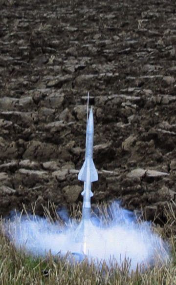
I flew the rocket from a standard Estes Porta-Pad, with no problem. It took off fast, staged nicely and came back for a perfect recovery. Grant Gibson, whom I was launching with, was quite impressed with the staging – I think the quickmatch helps in that respect.
Overall this rocket has been quite successful, and should fly again soon. I think the design could be refined to make it more accurate in terms of scale features, and it deserves a decent paintjob, but I am pleased with the results.
 |
 |