| Manufacturer: | Scratch |
READ TOP TO BOTTOM IN EACH COLUMN
|
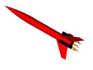
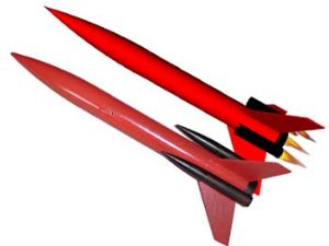
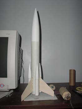
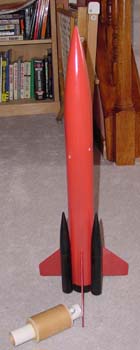
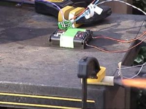
The initial concept, rendered in Rocksim.. The rocksim export, next to a picture of the actual Rocket I tested several battery configurations to determine the lightest possible reliable combination. Apparently, 3
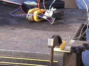
AAA cells is sufficient to light an Estes ignitor if they are fresh. I was also testing the perfectflight timer that
will be used to ignite the sustainer(I hope)
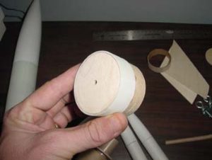
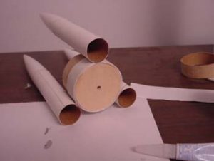
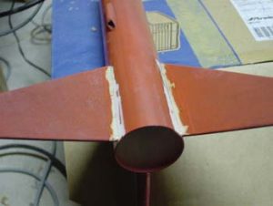
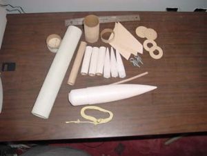 The humble beginnings of the booster, pretty simple, a bulkhead placed in the bottom of a short piece of fibre
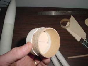
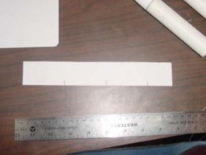
glass tube, with a short piece of coupler to attach it to the sustainer. 5 minute epoxy holds it all together... Different angle, same part.. I will likely nuke this page later, as it adds no content.. Wow, a picture of the fin placement template! I bet this one gets deleted too! Well, since it is here, I
measured the circumference of the tube(OD), Divided by 3, and marked a pice of paper in the appropriate locations, the
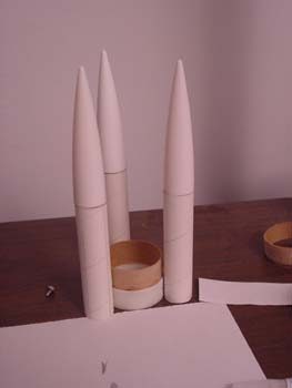
marks were then transfered to the sustainer, and the booster, to located the fins and the booster motor tubes.. The almost finished booster...The motors(24mm) will be retained with masking tape, and use a masking tape thrust ring as well. The booster has 3 24mm motor tubes, and should provide enough power to get it off the pad safely. The nose cones will be attached with 12" nylon cord scavenged from ear plugs. MMM, more angles.. All put together..You can see the sustainer motor assembley next to it, wow huh!
|
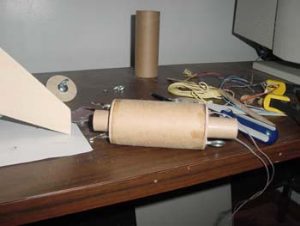
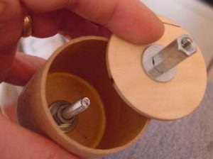
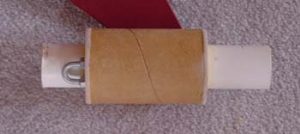
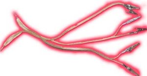
This is the 24mm sustainer motor mount. As it is rear eject, it is removable. You may notice the clips on the
bottom, hopefully they will carry the current which will light the sustainer motor. At apogee, the engine assembly will
be ejected, pull the chute out the bottom, and carry it safely back to earth...I also made a 29mm engine assembly so it
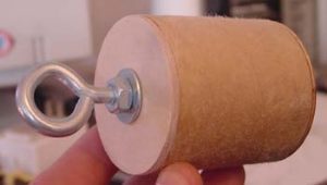
can fly in different configurations. Each of the engine assemblies also features an eyebolt to attach it to the shock
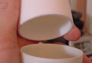
cord. They were constructed with wood glue, as opposed to epoxy. This would be the battery bay, it will fit all the batteries I want, along with the perfectFlight Timer, with
loads of room to spare. This is inserted in the top of the airframe, and held in with a piece of coupler (glued
inside), and secured on the other side by the NC, which is held on with 2 screws for flight. You may notice, there is
an eyebolt attached, as this is where the shock cord is attached to the rocket. There was really no need for the bulkhead on top, but who knows..I wouldn't want the batteries to be able to
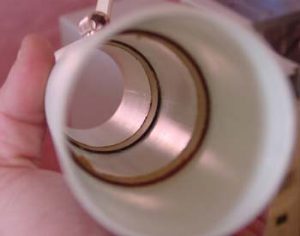
leap up into the NC anyway... This would be the inside of the airframe. Notice the couplers, one basically acts as a thrust ring, while the
other keeps the battery bay in the airframe. MMMM Fillets...the airframe was roughed up quite a bit prior to applying the epoxy. The bottom was removed from the NC to provide a little more room. Just after being primed, the rocket took on a little damage, a la kidsamine... All better now... All ready to go, also in the picture is a 29mm motor mount, so the sustainer can fly on it's own.. This would be the 29mm Motor mount all by it's lonesome. All of the wood and paper parts were bonded with wood
glue, as opposed to epoxy. Another VERY exciting timer test.. I needed something to light a cluster..so I guess this came with the project.. Flight Report |
||||
 |
 |