| Manufacturer: | Scratch |
THE TURNOGIVE !
Michel Demey's Descon-13 Entry
Warning: this thing is not flyable!
What is it? An automatic device that can cut an ogive from Styrofoam...
I was the author of a first device to do that manually. It was described in the Apogee newsletter of August 2002.
It used two identical templates and a hot wire to make ogives. But this first try had a problem: New templates had to be made for each size. And I don't like to make templates. A new idea had to be found.
Here it is!: this new model is motorized and automatic. Not very fast, but you can let it work and meanwhile read the last Apogee newsletter... And it is adjustable.
The little inconvenient is that the only shape it can make is an ogive.
General view
Note: click on the drawing to see picture...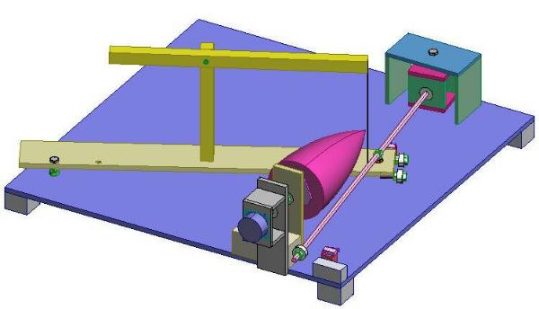
How it works?
A hot wire saw is mounted on a pivoting arm that is moved by a first motor
coupled to a threaded rod.
The Styrofoam bloc is mounted on a rotating plate that is powered by a second
motor.
The blue plate is the base, with five small feet, one at each corner and
one in the center. It is a square 600*600 mm made from 9mm thick plywood.
There are three main assemblies:
- The rotating arm with the hot wire saw is at left.
- The rotating support of the Styrofoam block is in front.
- The motor for the arm is behind, with the threaded rod.
The size of the machine
I needed ogives with a diameter of 60mm. So I build the machine with that size in mind. I think it can make ogives from 40 to 100 mm without problems. You can adapt the size of the base and the arm to the range of sizes you need.
Assembly 1: The mechanism used to rotate the Styrofoam block:
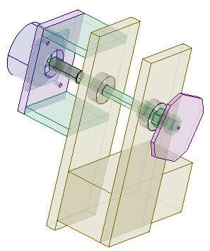 This assembly
uses two ball bearings.
This assembly
uses two ball bearings. All the ball bearings used to build the machine are found in rollerskates. You can buy them by pack of 8 in any good sport shop. The outer diameter of the ones I found was 22mm. Inner diameter was just 8mm, ideal for a threaded rod. You guessed: all the bolds, nuts, threaded rod are of 8mm.
Find your ball bearings, and buy all the rest with the inner size of them.
The stepper motor is of unipolar type, found in an old matrix printer. Unipolar motors are the easiest to drive. I will describe later the electronics used to drive the machine. It is intended for unipolar motors only.
How to know if you have an unipolar motor in your hand? There are 5 or 6 wires.
The stepper motor is coupled to the threaded rod with a small piece of flexible plastic tube. This is also the easiest way to do that. Gears or pulleys could be use, but believe me, it is harder.
The block mechanism is not fixed to the base. It can move laterally, to put the hot wire at the correct position for the size you need. It is maintained in place with a screw clamp.
Assembly 2: the arm.
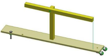
You can see two little wheels at the moving end of the arm. This is the best, but is not absolutely necessary. My first version, that worked, used only two blind nuts that slipped on the base.
The hot wire holder must have a system to tense the wire. See the pictures
for an example of how to do it. You can find interesting information about hot
wire cutting, power supply, etc on the web.
Assembly 3: the arm motor box.
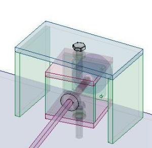 Since the arm
end moves, the threaded rod motor holder must be able to rotate. Since the arm
end moves, the threaded rod motor holder must be able to rotate. The arm motor box has only one ball bearing. One bold hold it to the base. Another holds it to a sort of bridge that covers it. All this mount is not glued to the base, because I was not sure of the final position. In fact, it will surely be in a different place depending of the size of the ogive made. |
Last details
the moving end of the arm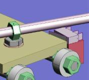 I used a simple nut to drive the arm. It would be probably better with a coupler, but a nut works. It is soldered on the head of bolt. The whole must rotate. On this detail view appears the end of course contact switch, that reverses the motion of the arm each time it is activated. |
the moving end of the rod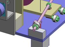 The end of the rod moves from left to right. I
chose to put a ball bearing there also. Adjust also the nut of the arm to align the whole. The width of the block should surely be adjusted if another size of ogive is made. Don't forget it. |
Electronics
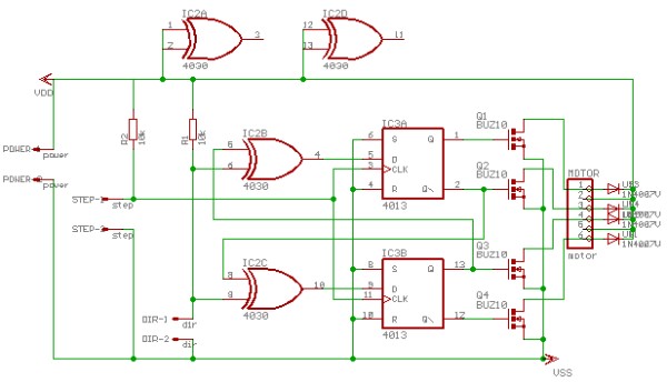
I could have used a computer controlled electronics. But I wanted you be able to build the machine without that. Here is a simple electronics that do the work.Motor driver
Here is a simple stepper motor driver schematics. It uses simple, easy to find IC and can be built on a striped board.Power supply for the two boards can be done with a 12V battery. Keep your adjustable supply for the wire
How to connect the motor wires?
- There are 6 wires, forming two circuits of three wires. First identify the two circuits.
- Choose one wire and connect it to your ohmmeter.
- Find three other wires that have no connection with the one you chose. Mark them: this is the first circuit.
- ... the three others are from the second circuit, of course!
- For the first circuit:
- Choose one wire and connect it to your ohmmeter.
- Check the resistance with each of the remaining wire.
- If it is the same, the wire you chose is the center. Mark it.
- If not, choose another one. And repeat until you find the center.
Left and right seems to have no importance. If you exchange them, the motor turn in the opposite side.
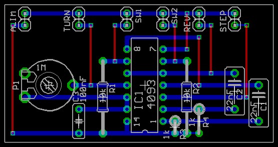
Build the circuit on a striped board:
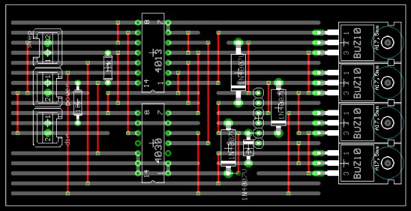
The red lines are top side wires. Use the connectors you find. Shift the component left or right if necessary.
Driver of the driver (flip flop)
To drive the two driver board, you can use a computer (pentium 6, 1Gb ram, 1Tb hard disk), or the following circuit!
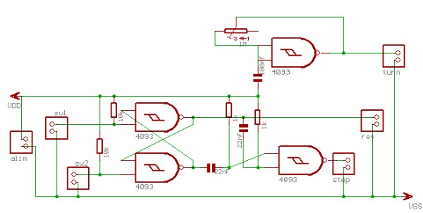
- rev and turn to the driver that controls the threaded rod motor
- step to the driver that controls the block motor.
| Detailed plans | Gallery |
 |
 |