Scratch Semi Three Original Design / Scratch Built
Scratch - Semi Three {Scratch}
Contributed by Dennis McClain-Furmanski
| Manufacturer: | Scratch |
Brief:
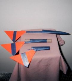
This LPR model breaks into three pieces at ejection, each section descending as
a "maple leaf" recovery monocopter.
Construction:
The parts list:
- 3 BT-20 tubes, 3.5" long each
- 1 BT-20 balsa nose cone
- 3 piece of basswood stock of 18" x 3/8" x 1/8", which is cut into 9", 6", and 3" lengths to be used as fin standoffs
- 1 2.75" engine hook
- 2 BT-20 tube couplers, 1.5" long
- 1 BT-20 tube or coupler, 1/4" long
- 1 1/16th" balsa sheet, 3.5" x 7" with grain parallel to 7" side
- 1 1/8" launch lug, 2" to 3" long
- 1 piece of scrap vinyl striping tape, vinyl decal or similar, 1/2" x 1"
Keep in mind that this was a successful experiment done on-the-fly. Other dimensions and/or materials may work better, but this worked for me. Glue is wood glue unless specified.
Cut balsa sheet into 3.5" squares, then cut the squares diagonally into four right triangles, for three fins and one scrap piece for cutting reinforcing spars (when used, cut these parallel to grain).
Glue in nose cone on top tube. Cut very narrow slit 1/2" long in tube from base of nose cone shoulder down. Cover slit with vinyl or paper and tack in place with CyA across top and halfway down each side. (This acts as a vent for excess ejection pressure). A small scrap sliver of balsa slid under the vent cover while gluing will ensure the cover doesn't get glued shut.
 In the middle
tube, glue 1.5" long couplers 1/2" into each end of tube, leaving
1" exposed. Sand exposed portion down, test fitting other tubes onto the
couplers so that they slide on and off easily with slight pressure but don't
slip due to gravity or shaking. You are looking for a loose but acceptable fit.
Graphite powder rubbed into the sanded coupler will improve sliding.
In the middle
tube, glue 1.5" long couplers 1/2" into each end of tube, leaving
1" exposed. Sand exposed portion down, test fitting other tubes onto the
couplers so that they slide on and off easily with slight pressure but don't
slip due to gravity or shaking. You are looking for a loose but acceptable fit.
Graphite powder rubbed into the sanded coupler will improve sliding.
Cut a slit in the bottom tube and place engine hook as normal (2.5" or slightly less from aft end). Test fit against middle tube. Top of engine hook should not prevent complete joining of bottom and middle tubes. Tack motor hook in place with CyA. Cut 1/4" length of BT or coupler, removing 1/4 to 1/3 of its circumference. Place this cut piece over top 1/4" of engine hook and glue with CyA, leaving the cut gap on the opposite side from the engine hook.
For the fin standoffs, you want cut and sand them as follows:
- On the 9" fin standoff, mark one edge 3" from end and then cut steep diagonal between this mark and end of the unmarked edge. Sand the diagonal cut to a very steep bevel so that when the sanded bevel is placed against the tube, it should form a smooth transition around the curve of the tube to a flat tangent on the outer surface of the standoff.
- Repeat this with the 6" standoff but only 2" from one end.
- Repeat this a third time with the 3" standoff but only 1" from one end.
- Glue and fillet standoffs to tubes with the sharp point even with the top of each tube. The 9" standoff is attached to the Top tube, the 6" to the middle tube, and the 3" to the bottom tube. Make sure that the standoff is placed in the gap cut in the engine hook anchor on the bottom tube!
- Glue and fillet a balsa triangle 1.5" from the end of each stand off so that the balsa grain is parallel with the leading edge. This will leave ~6" of the balsa hanging off the end of the standoff.
- Glue 1" x 1/8" slices of scrap balsa along surface of stand off and fin "root" (long edge) for reinforcement. This can be done on all fins but is especially important on the long (9") standoff.
Glue launch lug to the middle tube along the top side of the standoff root.
Finishing:
Coat entire rocket heavily with sanding sealer twice to stiffen as well as
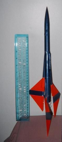
fill, sanding the wood after both coats. Prime and paint. High contrast/high
visibility is required. Original was cobalt metal flake blue and fluorescent
orange (as pictured). Fins were painted with dark stripes on orange fin so that
when spinning they'd make a circle. They looked like semaphore flags, but there
were only 3, hence "Semi-Three".
Flight:
All three pieces were individually flight tested (hand thrown) with a spent
engine casing in bottom tube. All three started spinning within 10 feet of
apogee.
First flight test: A8-3. Straight boost, ejection at apogee, complete separation, all spun and recovered as intended. Remained easily visible during entire flight.
Second flight test: A8-3 plus top tube filled half way with tracking powder. Straight boost, ejection at apogee, tracking powder not much help. Complete separation and all three pieces descended as intended. Bottom tube lost in tall hay.
New bottom section was built. All sections had more orange painted on body for better on ground visibility, however, a short cut recovery field is recommended.
First public flight, METRA, Pine Island NY 09/04/2004 with B6-4. Nice cut grass field. Stability rightfully questioned by RSO and expected. (That's why two private test flights first.) Boost straight, rocket went out of sight during ascent but at ejection there was complete separation and all 3 became visible, spinning as intended. There was a number of positive comments by the spectators. All parts landed within two seconds and 20 feet of each other.
Recovery:
No recovery wadding is needed for flight.
Summary:
As noted, this was an experiment on-the-fly that worked. You are encouraged to
experiment with the design but test it safely. If separation is not complete,
two pieces will come down, one of them not spinning, which means further
sanding or lube of the joint that didn't separate is needed.
High visibility is the key to complete recovery of all pieces. This means both the rocket and the field. If any portion of the fin/stand off construction seems weak and likely to flutter, feel free to add some small balsa stiffening spars; small pieces aren't likely to change the recovery characteristics by much.
 |
 |