Descon 6 Toose Dager Original Design / Scratch Built
Scratch - Toose Dager {Scratch}
Contributed by Steve Bloom
| Manufacturer: | Scratch |
Assemblage:
 Assembly:
Toose Dager is a 2-stage rocket design which incorporates all of the latest technology and special features that are seen on the flying range today. From the staging timer mounted in the sustainer to the tubular nylon and high quality Rocketman parachutes the Toose Dager is designed to perform and last. The parts list is complete except for the electronics package. There are many brands of altimeters and timers on the market today and any combination of them can be used. Most will fit into a standard 3inch airframe 6 inches long.
Construction is straight forward and similar to most high power rockets.
Fins, Centering Rings and Motor mounts:
The thru-the-wall fins are bonded to the motor tube, two centering rings and filleted to the BT both inner and outer. A third centering ring is near the top of the MMT inside the coupler section. The fins are laminated with 3/32 plywood for stiffness and airfoiling. There is no fiberglass cloth used anywhere. The airframe sections are all short and stout and most are strengthened by internal couplers. There is a fourth ring added to the aft end of the sustainer MMT used for motor retention (BloomBolts) and igniter terminals.
Zipperless Design Features:
Both the booster and sustainer incorporate the zipperless features seen commonly today. The booster is motor ejection charge recovery only so therefore has holes in the upper bulkhead. The upper bulkhead in the sustainer fin can is solid. This coupler compartment is the timer electronics bay. The timer bay has a floor in it to also. An all-thread rod is used to attach the top of the timer bay with a wing nut. A U-bolt is mounted in this bulkhead for strong recovery tether attachment.
Key Construction Steps:
When installing the couplers, several of them bottom out on a bulkhead. Therefore, it is critical to bond them in the proper sequence with epoxy only in the right places.
The Staging coupler:
This coupler is bonded to the upper end of the interstage airframe and butts against lower CR (at the base of the fin tab) of the sustainer. For ultimate strength of this airframe junction, it is critical to have the coupler positioned so it makes contact with the CR simutainiously with the BT pieces meeting. To accomplish this, the coupler is slid into the sustainer until it makes contact with the CR. Then epoxy is smeared all around the inside of the interstage airframe. The airframe pieces are joined together and immediatly pulled apart making sure to extract the coupler without it moving in the interstage airframe. The coupler is now positioned in the interstage airframe precisely.
The Altimeter Bay:
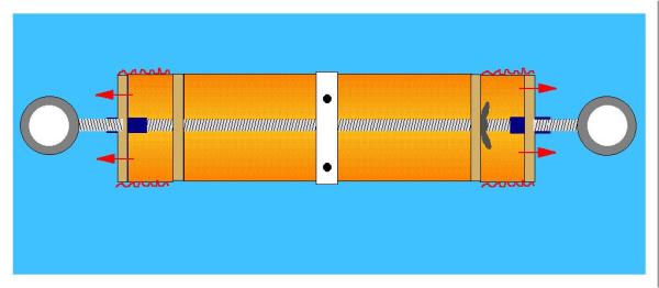
The altimeter bay is not a weak link in the airframe. It is held in place with all-thread rod and sandwiched between coupler rings and perforated bulkheads. This is done by assembling the altimeter bay, coupler rings and perforated bulkheads as a unit which positions them properly for bonding. With a 1/2 inch ring of BT bonded to the midline of the AB and the all-thread rod extending 1" beyond each end, 1" rings of coupler material are sandwiched between the AB bulkheads and the perforated bulkheads. The perforated bulkheads have 1"long coupler nuts bonded into them. Epoxy is then applied to the inside of the airframe segments which bonds -only- the perforated bulkheads and coupler rings. When dry, the AB is twisted and unscrews from the airframe.
Notes: The eyebolts extend 1/2" into the coupler nuts. The all thread rod goes in to the middle from the other direction. The red squiggly lines represent the bonded area. Epoxy is smeared on the inside surface of the BT to bond only the area shown. The left hand (brown) bulkhead on the AB is bonded on. The one on the opposite end is removable and held in place with a wing nut. The end bulkheads are perforated with 1/4 or 3/8 inch holes to allow the ejection charge to pressurize the appropriate area (arrows).
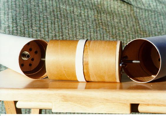
The altimeter is housed in a coupler with one bonded bulkhead (left) and one which is removable (right end). On the left airframe section you can easily see the threaded coupler nut and washer in the perforated bulkhead. An eyebolt is threaded into the opposite end of the coupler nut.
Also visible is the ring of phenolic coupler material which can be seen down by the perf. bulkhead. When the altimeter bay is threaded into the BT it stops when; The threaded rod bottoms out in the coupler nut; The bulkhead of the altimeter bay hits the phenolic coupler ring section; And the BT airframe (white) makes contact with the BT band (white) on the altimeter bay. (which needs 3 3/16 holes)
 The Booster:
The booster is just long enough to handle a J350. The fins are thru the wall to the motor mount. Not shown is the rail button which is screwed into the aft CR. Also, BloomBolts have been added to the aft CR for positive motor retention. (see sustainer)
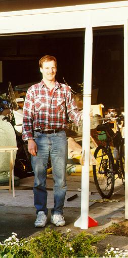
Finished Rocket:
It's about 8 feet tall when all put together. I plan on a first flight May 7th at our local club launch. An I300 in the booster and a G80 in the top half will keep it under 5000 feet out at Monroe. Later in May, in Oregon, I'll let it air out a bit more on an I300 to I161 or so. Then, down in Blackrock, why not a J350 to J350?
The Launch!
I had to strap on a couple of 1/2 inch launch lugs because I don't have a rail. I did all the prep at the house except igniter insertion and final chute packing. My buddy Mike Kallgren met me at the farm and we packed the chutes, checked off on the electronics, loaded it on the 3/8ths rod and installed igniters. Mike took the photos while I checked the range, skies and continuity. "SIG Captain Scarlet", all systems go!
The igniter caught fire and the nozzle emmited a small orange flame just a split second before the purple Blue Thunder boost of the H242S sent it off the pad. The launch was straight up, vertical. At 2 seconds the Olsen EZ Timer lit the upper stage G80 FWL and all Mike and I saw was a cloud of smoke. I watched the booster arc over and saw (and heard) the chute deploy. The sustainer kept climbing until a gradual arc at appogee triggered the Adept Alts2 drouge charge. I was really happy at this point but even more pleased when the main deployed at it's programed 600 feet AGL and the rocket landed safely out in the grassy field. Perfect first flight! The altimeter was beeping out 1511. My first 2 Stager!
| Body Tube BT 3.0 | LOC Precision | $7.10 X 2 |
| Phenolic Coupler Tube CTF - 3.0x36 | Public Missiles Limited | $9.95 |
| Fins - 3 PML A-05 | Public Missiles Limited | $3.45 X 3 |
| Fins - 3 PML B-09 | Public Missiles Limited | $4.95 X 3 |
| Nose Cone PNC 3.0 | Public Missiles Limited | $14.95 |
| Motor Mount Tube, MMT 1.52(38mm) | LOC Precision | $5.00 |
| Centering Rings (4) CR-3.0-1.5 | Public Missiles Limited | $2.25 X 4 |
| Centering Rings (3) CCR-3.0-1.5 | Public Missiles Limited | $2.25 X 3 |
| Bulkheads (5) CBP 3.0 | Public Missiles Limited | $1.45 X 5 |
| Bulkheads (8) BP 3.0 | Public Missiles Limited | $1.45 X 8 |
| Welded Eye Bolts, 1/4" (4) | Hardware Store | $8.00 |
| U-Bolt 1/4 X 2 | Hardware Store | $2.00 |
| Washers (4) large, (4) small | Hardware Store | $0.48 |
| Tubular Nylon, 9/16" (40 feet) | REI (stock #472315) | $8.80 |
| Parachute R3C | Rocketman Enterpirses | $30 |
| Parachute R7C | Rocketman Enterpirses | $45 |
| Parachute R24D | Rocketman Enterpirses | $20 |
| Rail Buttons (3) | Blacksky Corp. | $1.25 X 3 |
| "T" Nuts 1/4 x 6/32 (4) | Hardware Store | $1.35 |
| Motor Hooks, 10ga bare copper wire | Hardware Store | $0.28 |
| Threaded Rod, 1/4 X 12 (2) | Hardware Store | $3.50 |
| Coupler Nuts, 1/4 (2) | Hardware Store | $0.72 |
| Hex Nuts, 1/4 (4) | Hardware Store | $0.08 |
| Quick Links, 1/8 (4), 1/4 (1) | Hardware Store | $6.25 |
| Wing Nuts, 1/4 (2) | Hardware Store | $0.14 |
| Contact Strip | Radio Shack | $1.79 |
| Electrical Posts (screws and nuts) (4) | Radio Shack | $.25 |
| Total $210.09 |
 |
 |