| Manufacturer: | Scratch |
(Contributed - by Kelo Waivio)
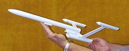
The Journeyman is a design I came up with after seeing one of those Quest all styrofoam Enterprise-E models. I'm kind of a Star Trek fan and always liked the asymmetrical style of the federation ships. The Quest kit "flew" at one of our club launches. It arced over and ejection occurred fairly close to the ground. Not all that impressive a flight from a commercial "kit". I figured I could get something to fly at least as good. I scratch build all my mod roc stuff so a kit was out. :-) The Journeyman is the result. It has flown on B6-4's so far and boost is very straight, but not very high, maybe 300 feet. It does let you see the whole flight at this altitude. I plan on putting it up on a C6-3 or a C6-5 the next time I launch it. I would be hesitant about a 18mm D, as the pylons are a bit long. I'm not sure how they would hold up to the aerodynamic forces. Maybe I'll try it sometime!
The design doesn't have a lot of detail, as it is kind of experimental. I plan on expanding on this concept and maybe going larger and more detailed on the next version. I'm still thinking about ways to build a non-tube based hull. Maybe from sheet balsa or foamboard. But, back to the subject.... Layout the patterns on your balsa stock and cut them out. Glue the three sections of the pylon fairing together and sand the edges round except for the front. I left this flat and later put on two small pieces of striping tape to simulate torpedo launcher ports. The main pylon can have the edges rounded except for the front. round these edges off after gluing on the fairing. Both root edges of the pylon where given a radius by sanding with a section of sandpaper wrapped around a section of BT50 tube. (use this method on the root edges of the nacelle pylon too) Cut the secondary hull section of BT50 at the angles shown on the drawing. I used a razor saw and lightly sanded the edges, then soaked the edges with CA to harden them, then finished sanding the edges smooth. The plugs for the ends are center disks from the Estes paper centering rings sanded to fit. The shape will be a little bit elliptical. The rear disk is recessed about 1/16" in at the bottom and about 3/4" at the top. The front disk is recessed 1/16" all around. I added white glue fillets to all the disks for extra strength and to fill small gaps. I then added a BT20 sized center disk to simulate the deflector dish. I was hoping for something more "dish" shaped but didn't have anything suitable on hand. Mark the tube with one line on center and one line on each side of it at 45 degrees for the root of the nacelle pylons. Cut the engine nacelle tubes to size with one end at a 45 degree angle. Soak with a little CA to harden before sanding. Assemble the nozzles and install in the angled rear of the pylons as shown in the detail. Glue in the nose cone in each nacelle with a bit of 5 minute epoxy. I used the conical PNC type that comes with the Estes PNC20 nose cone pack. Rounded or ogive shapes would also work, it's more a matter of what looks best to you. The conical ones where "in stock". Mark a guide line along the main BT50 and glue on the main pylon and the forward fairing at the positions shown. I used 5 minute epoxy tacked in place with thick CA. I added small white glue fillets after the epoxy set. Add the launch lugs to each side of the pylon and forward fairing only after all the fillets are in. I would also suggest spacing them out with a small 1/16" thick balsa strip to keep the rod from marring the side of the body tube after it's painted. I glued on the rear lugs first then used a small section of 1/8" rod to align the forward lugs with the rear. Glue the nacelle pylon fairings to each end of the pylons adding in the filler piece to the front and the rear. Sand smooth after the glue dries. I used Yellow wood glue for the balsa to balsa joints. Sand a radius to each pylon root with a piece of sand paper wrapped around a section of BT50 tube. Assemble the motor mount. I used an engine hook bent from a section of 1/32" music wire. The aft centering ring is 3/4" from the motor end, the front ring is flush with the tube end. I used a Kevlar® shock cord mount (1/32" diameter from Apogee Components) and secured it to the forward centering ring. I drilled a small hole between the tube and the ring and fed the cord through it and tied it in a loop around the motor tube. I have also used Kevlar® and the old slit and glue method for shock cord mounts. I am beginning to prefer this method as it keeps the cord mount a little farther away from the ejection end if the motor. The slit is easily filled and smoothed with a little Elmers Fill-N-Finish or similar wood filler. Or just use your preferred method and materials. Glue in the motor mount so the motor tube end is flush with the back of the main body tube. Glue the secondary hull body tube to the pylon with 5 minute epoxy. Center the pylon on the middle guide mark on the body tube. Glue the nacelle-pylon assemblies to the secondary hull centering the pylon roots on the guide marks. Add white glue fillets to the fairing/hull joints. Make sure the engine nacelles are parallel with the secondary hull and the main hull body tubes. I used a 18" diameter octagon chute made from red metallic mylar "wrapping paper". This size works well. You could also go with an 16" chute for windy days or smaller fields. I've flown it with each size. The second flight had the 16" chute and it was fairly breezy. It had very little weather cocking during boost. Drift isn't too big a problem with this bird. I didn't add any nose weight to the plastic nose cone. The CG is just in front of the forward pylon/main hull joint with an engine installed. I have no idea where the CP would be on this thing so I guessed! I would think it's a ways back because of the long pylons and the engine nacelles. I painted mine all white. The photo was shot before I added 1/8" wide red striping tape trim. The deflector disk was painted red. The engine "nozzles" where painted flat black. I ran a stripe down each side of the main hull with a break near the middle. I added the registry number NCC 72132 (my NAR #) in the gap. I also plan to add the name to the front of the main hull just behind the nose cone. I used small adhesive back lettering and had to cut each one out and stick it in place. This was kinda tedious, a custom decal would have been easier. If anyone is interested I can email you cad files for the patterns. I can supply them in AutoCad ".dwg" for release12 and 14, or in ".dxf" release 12 or 14. Email me directly if you would like these formats. My email address is waivlink@aol.com Parts list; standard engine mount Estes EST-303157 engine mount kit 16" or 18" parachute |
| Please use your view image facility to display them clearly at full size |
 Click to enlarge |
 Click to enlarge |
 Click to enlarge |
 Click to enlarge |
Sponsored Ads


 |
 |