| Manufacturer: | Scratch |
VECTOR
by Scott Hamlin
Features:
|
 |
Intro:
 When I read about the kit-bask theme of DESCON-X, I thought it
would be a good idea to try several staging and clustering ideas that I had
been thinking about. My first idea was to build a "sleeper" Gemini DC
by making the rocket appear stock while using a 24 mm center engine mount with
two outboard 18 mm mounts. Simulations indicate that air staging an E9 to two
C6-7's would result in an altitude of about 1000 meters. Lots of fun! So I
purchase a couple of G-DC kits. Before they arrived, I saw another G-DC at
Orangeburg that was very similar. In this case, the basher used the standard 18
mm center mount and two 13 mm outboards. On the way home, reconsidering my
approach, I thought the sleeper approach was probably too common and that
someone else would probably do it. I still have most of the g-dc parts from one
kit and an unopened kit. I'm thinking about putting the two together to make a
Modroc with four outboardsa
When I read about the kit-bask theme of DESCON-X, I thought it
would be a good idea to try several staging and clustering ideas that I had
been thinking about. My first idea was to build a "sleeper" Gemini DC
by making the rocket appear stock while using a 24 mm center engine mount with
two outboard 18 mm mounts. Simulations indicate that air staging an E9 to two
C6-7's would result in an altitude of about 1000 meters. Lots of fun! So I
purchase a couple of G-DC kits. Before they arrived, I saw another G-DC at
Orangeburg that was very similar. In this case, the basher used the standard 18
mm center mount and two 13 mm outboards. On the way home, reconsidering my
approach, I thought the sleeper approach was probably too common and that
someone else would probably do it. I still have most of the g-dc parts from one
kit and an unopened kit. I'm thinking about putting the two together to make a
Modroc with four outboardsa
Another idea I've been considering is staging a D to two or three B's or C's. My theory is that if there is a moderate separation between the stages, the burn through from the D will ignite all of the sustainer engines. Unfortunately, I needed a larger tube than was in the parts list for my concept, so I started thinking about staging a cluster to single sustainer engine. Then I thought about aiming the burn through of the boosters at the sustainer engine. This is how the Vector concept originated.
Design:
A concern in Vector's conceptual design was what would happen if one of the engines in the booster cluster didn't ignite. So, in order to make Vector stable even in the event of ignition failure, the thrust of each booster was directed at the center of pressure. If one (or two) of the booster engines failed to ignite, the Vector addition of the remaining engines would have an axial component (making the rocket go up) and a tangential component through the CP (making the rocket go horizontal). In theory if this occurred, the rocket would remain stable and vertically orientated; however, it would also "walk" horizontally. When describing this rocket to my engineer buddies, one of them told me that after a nominal flight, I would have to intentionally launch the rocket on only two booster engines. This inadvertently happened on the first flight (see flight reports.)
Booster Construction:
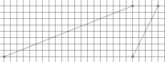
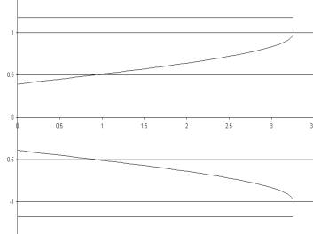 In order to Siamese the three BT-20 booster tubes together, they
must be cut with the proper shape. I solved the intersection of the three tubes
numerically and plotted them with my printer to be used as a guide (see below).
The scales are in inches. Each booster tube is 6" long, but if you overlap
the cutout area you can get 4 from an 18" tube.
In order to Siamese the three BT-20 booster tubes together, they
must be cut with the proper shape. I solved the intersection of the three tubes
numerically and plotted them with my printer to be used as a guide (see below).
The scales are in inches. Each booster tube is 6" long, but if you overlap
the cutout area you can get 4 from an 18" tube.
Cut a ¾" length of BT-20 from the scrap pieces. Glue the BT50-20 centering ring flush on one end. Glue each of the three BT-20 booster tubes to the ¾" length of BT-20. The top of the booster tubes should touch the BT50-20 centering ring. I used tape to keep the booster tubes aligned while the glue cured.
After the glue attaching the tops of the booster tubes has cured, glue the joints where the three booster tubes meet. After this glue has cured, use a ¼" wide strip of tissue paper to reinforce the joints and to plug any small holes.
Cut a 2" length of BT-50 for the booster shroud. Cut two ¼" holes (on opposite sides of the tube) centered 5/16" from the end (I used a hole punch). This end will be the top end of the booster shroud. Test fit the booster shroud by sliding it over the BT50-20 centering ring. The bottom of the booster vent holes should be flush with the centering ring. Glue the booster shroud on by applying glue to the centering ring and the area of the booster tubes when the shroud touches.
 Left: booster fin plotted on ¼" grid. The left side of
the booster fins guide is the leading edge. Cut the fins so that the grain is
parallel to the leading edge. i suggest that you lay out the sustainer fins
first though. Glue the booster fins to the booster tubes so that the trailing
tip is flush with the bottom of the booster tube. Use some thinned
fill-n-finish to smooth out the joints, paint, and the booster is ready for
flight.
Left: booster fin plotted on ¼" grid. The left side of
the booster fins guide is the leading edge. Cut the fins so that the grain is
parallel to the leading edge. i suggest that you lay out the sustainer fins
first though. Glue the booster fins to the booster tubes so that the trailing
tip is flush with the bottom of the booster tube. Use some thinned
fill-n-finish to smooth out the joints, paint, and the booster is ready for
flight.
Sustainer Construction:
The sustainer is a straightforward 3fnc (three fins and a nose cone) design. I used a D12-7 for the sustainer motor, but I fly on a huge sod farm. If your field is limited, you may want to modify the design to use an 18 mm motor mount.
The main body tube is 13 3/8" long. I added 2 oz of weight to the nose cone to further increase stability and to reduce the altitude. Even with the additional 2 oz, Vector Sims to 2300' with (3) b6-0 booster and a D12-7 sustainer motors! Place the launch lug at the center of mass with engines loaded.
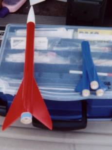 Sustainer Booster |
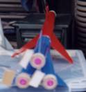 Vector loaded for bear |
Vector Flight Data:
 To prep Vector for launch, friction fit the D12-7 sustainer motor into the
sustainer leaving about ½" exposed. Wrap ¼" tape
several times around the bottom of the B6-0 booster motors and then friction
fit the motors into the booster tubes. Test fit the booster on the sustainer.
The booster should not fall off under when holding the sustainer; however, it
should not take too much additional pull to remove. Add tape to the D12-7 to
adjust the fit.
To prep Vector for launch, friction fit the D12-7 sustainer motor into the
sustainer leaving about ½" exposed. Wrap ¼" tape
several times around the bottom of the B6-0 booster motors and then friction
fit the motors into the booster tubes. Test fit the booster on the sustainer.
The booster should not fall off under when holding the sustainer; however, it
should not take too much additional pull to remove. Add tape to the D12-7 to
adjust the fit.
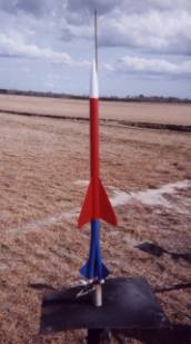
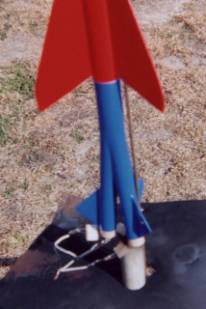
Left: Vector on the pad. Note clustering whips.
The first launch of Vector was at the February 9th ICBM launch at Orangeburg, SC. It was windy, and I waited all day, but the wind never died down. For the first flight, the RSO asked me to load Vector on a high power pad in order to provide more distance between it and the spectators.
At ignition, I thought all three booster engines lit (later I found only 2 did) the boost was straight with some weathercocking. Booster separation was good, the D12 lit, and Vector was almost out of sight.
A premature ejection caused the parachute to strip, but the sustainer tumbled down safely with the nose cone attached.
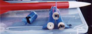 When I approached the booster I noticed two blue objects on the
ground. I thought to myself, "not good" upon closer inspection,
apparently only two booster motors lit on the pad. When the sustainer lit, the
thrust lit the third booster motor from the top, burning the booster into two
pieces. In the above photo, it is obvious that the booster motor on the left
never developed thrust out of its nozzle, yet the propellant was consumed. It
never occurred to me that could have happened I needed a new booster, but at
least I knew the Vectored thrust worked and the rocket was stable on only two
booster motors.
When I approached the booster I noticed two blue objects on the
ground. I thought to myself, "not good" upon closer inspection,
apparently only two booster motors lit on the pad. When the sustainer lit, the
thrust lit the third booster motor from the top, burning the booster into two
pieces. In the above photo, it is obvious that the booster motor on the left
never developed thrust out of its nozzle, yet the propellant was consumed. It
never occurred to me that could have happened I needed a new booster, but at
least I knew the Vectored thrust worked and the rocket was stable on only two
booster motors.
When I rebuilt the booster, I decided to build two, just in case. I flew Vector the second time on May 11, again at O'burg. Again, it was windy and I waited most of the day, but the wind never let up, so I swapped the 'chute for a streamer. Again, I used (3) B6-0's for the booster and a D12-7 for the sustainer. This time the RSO let me launch from the model rocket pads. At this close range, the Vectored thrust was very noticeable. It was obvious all three boosters were lit and Vector was screaming straight up. At about 200' the sustainer lit and Vector momentarily went out of sight. When I re-established tracking, Vector was on the streamer and recovery was nominal.
Lessons Learned:
The canted, Vectored motor design is unique and generated a lot of interest at the launch. The Vectored thrust is pretty cool to see. To insure successful cluster ignition, it may be a good idea to use better igniters. For the second flight, I soldered leads onto the solar igniters as I think the wire whips failed on the first flight. It may also be a good idea to paint the inside of the booster with high heat paint.
Finally, as I mentioned earlier it may be a good idea to use an 18 mm motor for the sustainer on the other hand, for the next launch, I plan to use (3) C6-0's for the booster and a E9-8 for the sustainera
 |
 |