DG&A High Power Rocketry L3 Armageddon
DG&A High Power Rocketry - L3 Armageddon {Kit}
Contributed by Drake "Doc" Damerau
| Manufacturer: | DG&A High Power Rocketry |
Brief:
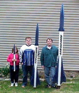
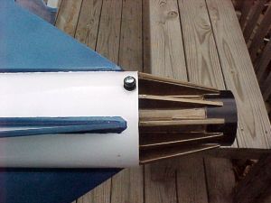
The L3 Armageddon is a single stage rocket with a very unique design. It comes
in your choice of a 75 or 98mm MMT.
Construction:
The kit comes with everything but parachutes. The all-thread, nuts, washers,
eyebolts, and shock cords are all included. The 5.5" body tubes are heavy
wall cardboard. All of the components are top shelf stuff.
This is not just a kit review. It's also how I used the kit for my level 3 certification. There is even some scientific testing data here that I performed. I am the plant Metallurgist and the Laboratory Director at Chamberlain Manufacturing, the operating contractor of the Scranton Army Ammunition Plant. This means I have millions of dollars of equipment I can play with on Saturdays, testing the materials we use to build our rockets.
When I decided to do my L3 at the 2003 NSL, I wanted to do something different than a 3FNC. A scratch built rocket would be easy enough but I didn't think I would have the time to work out all the details. My favorite commercial kit was the Armageddon by DG&A, so figured I would do my L3 with the DG&A L3 Armageddon. This is a 5.5" diameter rocket that is almost 10 feet tall. It's not even close to being my largest bird, but impressive nonetheless.
The next problem would be the motor. APCP was in short supply and the BATFE thing was looming over the horizon. OK, I'll go hybrid. I chose the Hypertek M970. It is a 75mm M fuel grain on the 2800cc L tank with the M injector bell. The L3 Armageddon easily adapted to the hybrid system because of the large fins and long body. The CP ended up being 2.1 calibers behind the CG with an empty motor.
The first thing you notice when you open the huge package is the quality of packaging. Each tube is wrapped separately and everything is carefully placed in the box. There was no damage to any of the components. A quick review of the parts list revealed that all the parts were there.
The airframe tubing was the heavy, 3/32" (0.078") thick walled cardboard tubing seen in other high quality kits.
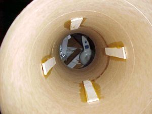
Securing the MMT and centering rings into the booster section
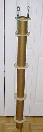 The MMT
assembly was constructed per the instructions. The hardware was tightened and
secured with epoxy.
The MMT
assembly was constructed per the instructions. The hardware was tightened and
secured with epoxy.
The motor mount tube was epoxied into the airframe by pouring 25 mL of epoxy onto each of the centering rings through the fin slots with a syringe. The assembly was first epoxied with the aft section up, to apply epoxy to the aft sides of the centering rings. Once the epoxy was cured, it was examined with a fiber optic bore scope. There were two locations that appeared not to be glued. Epoxy was again inserted into the airframe through the fin slots and the assembly was tilted in the direction of the questionable areas to allow the epoxy to flow into the area. When it appeared to be complete, the assembly was turned over and the aforementioned process was repeated to apply epoxy on the forward side of the centering rings.
No fiberglass was used for the airframe of this rocket. The 5.5" tube used in the construction of this kit was tested in my laboratory and exhibited a strength of 1312.7 lbs force before yielding. However, if any side forces are applied during acceleration we must examine column buckling loads. Column buckling formulas are fun and exciting, but to test the column buckling in real life, a piece of 5.5" airframe was tested by compression at a 8.5 degree angle. The force at yield was 886.4 lbs force.
Compressive and column buckling forces do not apply to the MMT/sustainer section due to the reinforcement by the fins and the MMT assembly. We therefore only need to look at the section forward of the fins. The forward section (with weights) including altimeter weighs ~5 pounds. The Hypertek M740 will exert a G-force of 23.16, thus 5 x 23.16 = 115 lbs. this is the maximum force applied to the airframe in an non-reinforced area. Inversely, we can surmise that we have a tube capable of withstanding 38.27Gs (886.4 /23.16 lbs = 38.27).
Compressive forces can be seen in the fin area during accent as well as landing, however as heretofore mentioned, most of this force is transferred to the CRs and MMT tube via the epoxy and thus its strength depends on the shear force of the epoxy. Therefore, there are virtually no axial forces on the tube at in this area. Virtually all of the forces on the tube itself are circumferential via any torque forces applied during flight or bending moment applied on the fins during landing.
To combat any bending moment applied to the fins, I looked at data seen in the r.m.r. HPR Strength of Materials Test. One of the discoveries made during the testing was on the fincans. The fincan that appears to be the strongest was one done by Mark Simpson where he used a strip of wood material along the fin-body joint. I used this method on the ID. Mark's method increased the strength of the joint over the next highest strength by 30% and by 200% over the average. It also prevented the tube from yielding at all during the fincan test and thus transferred the force to the fin making the joint stronger than the fin. I have no doubt that if the fin material was stronger, the value would have been higher. This appears to be sufficient to replace the fiberglass on the tube in this area.
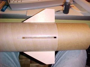
Fin assembly
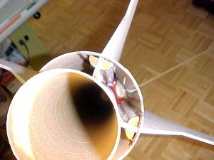 I
duplicated Mark Simpson's wood fillets in the L3 Armageddon. Pieces of corner
molding were used for this. The fins were epoxied in place then the molding was
inserted with copious amounts of epoxy. The aft CR was then epoxied into place
and the nozzle fins were added.
I
duplicated Mark Simpson's wood fillets in the L3 Armageddon. Pieces of corner
molding were used for this. The fins were epoxied in place then the molding was
inserted with copious amounts of epoxy. The aft CR was then epoxied into place
and the nozzle fins were added.
The large fins of this rocket are only 1/4" thick. To lessen the effect of possible fin flutter, a laminate of fiberglass was applied to the surface of the fins. This was accomplished using standard fiberglass lay-up practices.
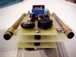
Payload section
The forward canard fins were installed "through the wall" per the instructions. In this area we have the coupler tube so they go through both the airframe and coupler tubes. The airframe and the coupler tube were joined first then the slots were cut for the fins. They were tacked in place with Jet Glue. Wood glue was then applied on the ID surface and allowed to seep into the wood and cardboard. The wood strips were applied while the glue was wet and generous fillets were then applied to the strips. Generous epoxy fillets finished the canard build.
The altimeters used are two Transolve PK6, a kit version of the P6. They were mounted to a piece of G10 with 316 grade stainless hardware and phenolic standoffs. The board was then mounted in the payload section using brass strips and tubing that slid over the all-thread. The brass strips were soldered to the tubing. The assembly is secured in the section when the nuts are tightened. This setup allows easy assembly and access to the boards. A hold down strap will further secure the batteries in their holders.
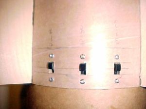
The safe/arm switches are redundant and consist of DPDT military grade slide switches. The three switches with their 6 functions control: power, apogee safe and main safe. This ensures that both altimeters are completely separate from each other with individual power sources.
The altimeter bay is sealed from ejection gasses. This is accomplished with the forward bulkhead epoxied into place and the aft bulkhead sealed to the custom centering ring with closed cell latex weather stripping. The altimeters used have been flown on several prior occasions. I have three of these units and they have always worked well.
Laundry and other recovery debris
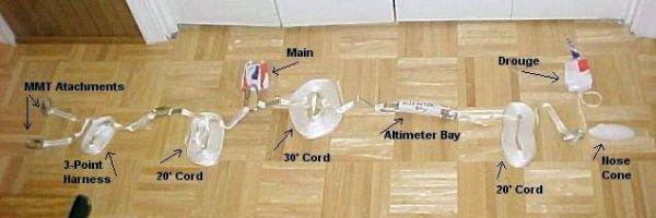
Recovery will be the typical two-stage method: drogue at apogee and main at 500'. One drawback with this kit is that the recovery for the main is aft of the payload section and the drogue is forward...or so it would appear. The section forward of the altimeter is only 11" and has one attach point. The section aft of the altimeter is 29" long and has the two attach points at the MMT. There is just not enough room forward of the altimeter bay to comfortably fit the main.
All shock cords are 9/16" tubular nylon. The drogue cord is 20' in length. The main consists of three cords. There is a 3-point attachment cord at the MMT attached to a 20' length of cord at which the parachute is attached. A 30' cord is then attached from the parachute to the altimeter bay.
Final assembly notes
I didn't do much in the way of aerodynamic shaping of the fins. Airfoiling the fins is done to reduce drag for greater altitudes but I like them low and slow. A more blunt leading edge increases drag by breaking up the air over the fins.
Vent
Every hybrid system needs a vent. For this I used a 1/4" ID large Aerotech igniter cardboard tube. After marking the location, I drilled a 1/4" hole through the airframe and the MMT. I then made the hole in the airframe larger to accommodate the OD of the vent tube and cleaned up the holes. Using the 1/4" drill bit as a guide passed through both holes, I epoxied the vent tube in place. I occasionally turned the drill bit to ensure it wasn't being epoxied to the vent tube. A X-Acto knife and some sand paper cleaned up the vent/airframe area and the job was done.
Motor retention
 Kind of
late to be thinking about this isn't it? I did put blind nuts in the aft
centering ring during assembly. The 6" long piece of all-thread looked,
well, kind of clumsy. I happened to pick up a 75mm Aero Pack retaining system
so I thought I would use it. It was hell trying to put it on after the nozzle
fins were already glued on! I used a Dremel saw to cut a gap between the fins
and the MMT long enough to insert the retainer. It made more work for me than
expected! The retainer was glued in with JB Weld and the gap between the fins
and the retainer was filled with wood putty. Oi!
Kind of
late to be thinking about this isn't it? I did put blind nuts in the aft
centering ring during assembly. The 6" long piece of all-thread looked,
well, kind of clumsy. I happened to pick up a 75mm Aero Pack retaining system
so I thought I would use it. It was hell trying to put it on after the nozzle
fins were already glued on! I used a Dremel saw to cut a gap between the fins
and the MMT long enough to insert the retainer. It made more work for me than
expected! The retainer was glued in with JB Weld and the gap between the fins
and the retainer was filled with wood putty. Oi!
Rail buttons
5/16" rail buttons were installed. The forward guide was installed with a 1/4-20 steel machine screw and nut, secured with JB Weld. The aft guide was installed by drilling and tapping the aft centering ring. The hole was filled with JB Weld and the guide was secured with a 1/4-20 machine screw.
Nose weight
Nose weight was added and was first considered to be used to keep the altitude to a reasonable level. Upon further construction, it was discovered that it was necessary to keep the CG forward enough to keep it stable using the HyperTek hybrid system. The rocket was unstable without the weight! A 3/8" threaded rod was inserted through the aft end of the nosecone and touches the inside of the forward end. 8oz of West Systems epoxy was then poured into the cone. The assembly was allowed to cure while in cold water, to prevent heat buildup and melting of the plastic cone. The remainder of the nosecone cavity was then filled with expanding foam. Threaded weights were then screwed onto the all-thread, followed by a coupler and an eye bolt. This arrangement keeps the weights off the nosecone and on the steel threaded assembly.
Finishing:
The entire airframe was sanded and a coat of Kilz primer was applied. The
paints used were Rustoleum white and metallic blue with a final clear over
everything.
Flight:
On the first flight, the motor lit and the bird leapt from the pad with
authority. The wind at ground level was only 6 mph but by the time she reached
2000 feet, she was gracefully arching into the wind. The 6.9-second motor
seemed to burn forever. If you have never heard an M hybrid motor, they can
only be described as sounding like a Pod Racer from Star Wars Episode One--a
loud roar coupled with a pulsating low-pitched jet-like sound. The few seconds
I lost it in the sky seamed like minutes. Then, there it was. Coming down on
its side with the drogue deployed. Falling, falling, falling... It's coming
straight at us! We ran about 20 yards to the left. 800 feet, 500 feet, 300
feet,... Where's the main?! Finally, at about 200 feet the main popped. It took
at least another 50 feet for it to unfurl. The main finally snapped open at 50
feet AGL and then landed 40 feet from the pad. That had to win closest to the
pad in the L3 cert column! A quick review of the rocket proved that everything
was in order and we had a successful L3 flight. Both of the altimeters chirped
out 4,200 feet.
The next four flights were on an AMW L777. For me, this is the best motor for this rocket. It brings it to just under 3,500 feet. I've also flown this rocket on windier days with a CTI K550 to around 2,000 feet.
Summary:
I love it! This bird is as different and unusual as it gets for any high power rocket. The flights on this (as well as the original size Armageddon) are truly awesome.
Even without the changes that I made, I did feel that the forward payload section was on the small side. I'm sure you could get a nice size main in there, but it would be a very tight fit. I would recommend actually making the altimeter bay shorter by changing the location of the forward bulkhead and using smaller altimeters. This would allow for more room for a main chute in this area.
The materials are the best I've seen for their types and the design is sturdy. The instructions contained page after page of high quality color photos and has many steps to clarify what the designer wants. Some of the steps in the instructions are somewhat ambiguous but then it is assumed one has a great deal of experience if they're building a level 3 project.
Related External Links
 |
 |