Modification Saturn V (29mm) Modification
Modification - Saturn V (29mm) {Modification}
Contributed by Tim Doll
| Manufacturer: | Modification |
 Brief:
The Estes EST 2157 1/100th Scale Saturn V is quite a nice rocket kit. Oh sure, its scale accuracy is not all that great, but it is readily available (at least as of this writing), reasonably priced at under $100 (with significant discounts available), large enough to be impressive, nicely detailed, and not terribly difficult to build. But it has one major shortcoming - it is woefully underpowered with its 24mm mount. Even an AeroTech E will only loft this Saturn V to perhaps 300 feet (although it looks and sounds darn impressive getting there). So I decided to solve the Saturn V energy crisis and built one with a 29mm engine mount - I figured it should be able to get out of it's own way with an F or G motor.
Construction:
Obviously, I started with an Estes Saturn V kit - actually I started with two Estes Saturn V kits. I built two Saturn Vs at the same time, one a "display" model, which I kept very close to box stock, and the other the "flyer" with the 29mm motor mount as well as various upgrades. This two at once technique yielded some advantages - I could pick and choose, using the 'best' parts on the display model. Also, the 'stock' display model provided a baseline on the rocket CG that was quite helpful when it came time to balance the flyer.
In addition to the Estes kit, I needed a 29mm, 15" long engine mount tube (note that this engine mount tube was 1.5" shorter than stock), 29mm engine block, and engine hook (from AeroTech). I didn't think the flimsy vacuum formed fins and fin fairings and that fragile escape tower would stand up to the higher impulse, so I contacted Mike Schmidt and got a set of "Moldin' Oldies" cast resin fin-fairing assemblies and Apollo capsule. I added a length of 5/16" aluminum tubing to use as an internal launch lug, and I tossed the stock parachutes and shock cords into the spare parts box, replacing them with nylon 'chutes and Kevlar shock cords.
 Modifications:
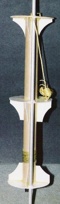
To build the engine mount, I started out with the stock centering rings, enlarging the center hole for the 29mm mount tube. I then took the top and bottom centering rings, and laminated 1/64" plywood to both sides of the rings - cut the plywood to size, glue to the centering ring with yellow glue, wrap in waxed paper, and place under some heavy books to dry. After installing the engine block and hook but before I glued the (laminated) centering rings on the stuffer tube, I stacked the centering rings and drilled a 11/32" hole through all three for the internal launch lug, with the outside edge of the hole 1/8" in from the outside edge of the ring (to clear things like the coupler to the upper stage). When I glued the centering rings to the stuffer tube, I used the aluminum tube to insure alignment of the holes. Gussets were then cut from the scrap centering ring card stock and glued in place to support the centering rings. After attaching a ten-foot length of .100" diameter Kevlar shock cord to the front of the engine mount, the whole assembly was liberally filleted with yellow glue.
When I epoxied the motor mount into the main body tube, I located it an additional inch forward from aft end (4 3/8 inches, rather than the stock 3 3/8 inches) to help keep the rocket CG as far forward as practical. I also fit pieces of 1/8" thick balsa between the main body tube and the upper and lower extensions of the internal launch lug, and epoxied those in place. Note that the shorter engine mount tube allowed me to move the engine forward, while preserving an adequate parachute volume for the large nylon parachutes.
Construction of the remainder of the Saturn V was pretty standard. A Kevlar shock cord was added to the 2nd stage - 3rd stage transition during assembly. The wraps were aligned such that the internal launch lug would exit in the large black section of the 2nd stage - 3rd stage transition wrap (to make it less visible). The wraps were attached using the recommended 3M Super 77 spray adhesive, then the edges were sealed used the Apogee thin CA technique (something of a belt and suspenders approach). Since they require no assembly, the cast resin fin-fairings are much easier to deal with than the stock vacuum formed plastic. After sanding the proper contour (using coarse sandpaper wrapped around the BT101 body tube), I simply glued the resin fin-fairings to the bottom wrap with CA, and then added epoxy fillets. The "extra" BT101 coupler was used as a reinforcing ring to prevent the upper third stage assembly from slipping aft into the lower section.
For recovery, in addition to the fore mentioned Kevlar shock cords, I replaced the stock Estes 'chutes with nice nylon parachutes and increased the 'chute areas to compensate for the higher weight - a (single) 36" 'chute for the lower section, and a 24" 'chute for the upper section. I maintained the harness arrangement for the upper section, again using Kevlar line for the harness.
 Flight:
I used the display model that I was building at the same time to do a CG check - prepped with a D12-3 (but unpainted) the CG was 23" aft of the tip of the capsule (that is pretty much even with the aft edge of the ullage motors). I also used RockSim to check the CP, which came out 25" (Barrowman) or 26.3" (RockSim) aft of the Apollo capsule tip. I epoxied 3.5 ounces of lead shot into the resin capsule, which provided a CG 22" aft when flight prepped with a G64 RMS (the heaviest engine I ever expected to use), giving a nice margin of stability. The completed Saturn weighed in at 19 ounces - 12 oz. for the lower section, 7 oz. for the upper section (including the 3.5 ounces of lead ballast in the capsule).
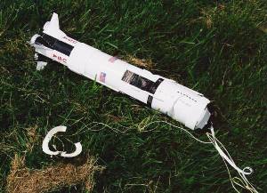
For the maiden flight, I selected an F40-4W RMS. It was magnificent - the Saturn ripped off the pad with the characteristic roar and smoke of a White Lightning motor. It climbed to about 500 feet, hung there for second before it slowly arced over, then came back to earth ballistic. That's right, a complete lawn dart - the ejection charge never fired. Worse, since it was an RMS, it was probably my fault although I don't know what I might have done wrong (I've launched a large number of RMS motors and this is the first time the ejection charge has failed to fire). The impact utterly destroyed the upper half of the rocket (basically everything down to the inter-stage wrap). Surprisingly, the resin Apollo capsule was the exception - it survived almost unscathed, just a (easily repaired) break in the escape tower (although it took a couple minutes to dig the capsule out of the crater). The engine mount held up surprisingly well - the forward bulkhead was broken into several pieces and the upper couple inches of the engine tube were buckled by the impact - but the rest of the mount was undamaged.

Summary:
While I'm naturally unhappy about the untimely demise of my 29mm Saturn V, I consider the modification a complete success. The engine mount demonstrated impressive strength in surviving the impact, so it should easily hold up to the 'normal' forces of numerous 'F' and 'G' powered launches. The 22" CG location provided a highly stable launch (in fact I could probably get away with less nose ballast), and the launch with an F engine was spectacular (so was the descent, but for the wrong reasons). While this Saturn is damaged beyond "economic repair", I've salvaged the resin fin-fairings and Apollo capsule, and construction has already started on another 29mm Saturn V.
Related Products
 |
 |