| Construction Rating: | starstarstarstarstar_border |
| Flight Rating: | starstarstarstar_borderstar_border |
| Overall Rating: | starstarstarstarstar_border |
| Manufacturer: | Modification |
Brief
A largish 2.6 inch rocket with a 24mm motor mount. This kit is pretty nice built stock, but came out before the new E9 motor was available. My version includes a motor mount that can accommodate this new product, as well as the new F21 from Aerotech. It also includes an ejection baffle, and fins that go through the wall made from basswood that are not a part of the original kit.
Construction
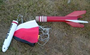
The kit comes in a very colorful box. All parts are typical good Estes quality. The balsa is a tiny bit softer than I'd prefer for something this size, and the die cruncher could stand a little sharpening, too. More on this later. The cone is a typical plastic cone that will require some work clearing the flashing away and sanding the mold lines before it will produce a smooth appearance. The 'chute, motor mount parts and shock cord come together in a plastic bag. A very nice bright red decal sheet is also included. As always with Estes kits, a well written and illustrated set of instructions make the kit complete. 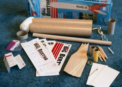
The balsa fins that come with this kit are perfectly fine and I would have no trouble using them and flying it that way on even an F motor. But since I'm already cutting a set for a scratch built Super Ranger project it's easy to just go ahead and cut a set for this rocket while I'm at it. The new fins are of 1/8 basswood, and go through the airframe and attach to the motor mount. Through the wall fins are hard to break off; I like basswood because it isn't a whole lot heavier than balsa, but it is a lot harder and the grain won't require so much sanding and filling. So a set was cut, complete with a tab to pass through the wall and with a notch in the root edge to accommodate the motor hook retaining tube. The fins were sanded round on all edges except for the root and tab.
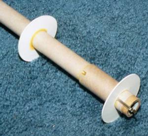 The two centering rings at the motor end were glued on per the instructions except that the forward motor ring was a little bit farther forward to allow for the fin tab. Since the new E9 motors are a bit longer than the D's I located the motor block 90mm in and set the hook so that it hangs over the end 5mm. A 95mm motor will now fit perfectly. The hook was not passed through the wall of the motor tube as shown in the instructions because it would get in the way of the longer motor. It was bent back on itself instead, and hooks on the retainer tube. A spacer will be required when using normal D size motors. This spacer is cut from an expended D12 and goes into the motor mount ahead of the new motor, and is removed when using the longer E9.
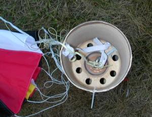
The rocket also uses a pair of centering rings at the front of the stuffer tube to add strength to the two piece airframe. This arrangement can be used to make an ejection baffle with just two additional parts and very little weight gain. First, the third centering ring was glued onto the tube 5" from the top. Then a plug was glued into the top of the motor tube; this plug is simply a stack of balsa disks glued together. A BT-50 size balsa block would also have worked. The block was soaked with CA to help protect it from the hot ejection charge. Next, a group of holes was cut in the tube between the plug and the centering ring. I'll normally cut the holes in three rows evenly spaced around the tube, each row having three or four 1/4 inch holes. Next, a 5" piece of BT-60 was cut from stock and a similar set of holes was cut in it. The edges of the holes were touched with thin CA on both parts. The BT-60 was glued to the last of the rings. Three equally sized and spaced notches were cut out of the edge of the ring - the remaining tabs are centered over the rows of holes. I wrapped one end the Kevlar shock cord around the top of the BT-60 and glued it there where the two parts meet. A loop was tied in the Kevlar a couple of inches above the baffle and one end of the elastic that came with the kit was tied off there. The other ends of both the elastic and the Kevlar will be tied to the nose cone.
A set of fin slots was cut in the body tube the width of the fins. The motor tube was then glued into the bottom of the rocket, the joiner ring added to that, and the top part of the baffle was glued in and oriented such that the rows of holes in the stuffer tube are centered between the rows of the BT-60. After all that dried the top part of the airframe was glued to the joiner. I had a bit of trouble with the two halves not matching perfectly at the joint. The top half is a tiny bit larger in circumference than the lower half producing a sort of hump in one spot. I spent a good deal of time working on this to minimize the potential hump back appearance it might cause. Finally, the fins were glued in. I used yellow glue for everything on this kit, except for the fin fillets wherein I used epoxy. Epoxy produces perfectly smooth fillets but it adds a lot of weight so it's important to avoid getting carried away.
Rating: 4 This was an easy but fun to build kit.
 Finishing
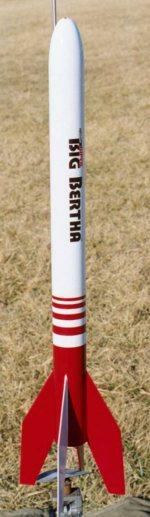
Finishing wasn't difficult; I started by sanding the mold lines out of the nose. Next the spiral groove in the body tube and the tube joint line was filled with Elmer's Fill 'n' Finish Wood Filler and sanded. The spiral sometimes takes two layers of filler in places and I already mentioned the problems with the joint. The whole thing was lightly sanded and wiped clean before being sprayed with a coat of Rustoleum white primer. The fingerprints and other minor blemishes could now be seen and were sanded away or filled as needed. The whole thing was then sanded with 400grit paper until all the parts could just be seen through the primer. After being wiped clean carefully, a second coat of primer was sprayed on and when dry lightly sanded again. The base finish coat was applied and a nice smooth finish was produced. The rocket stood around for a week or two and then was masked off for a highlight coat. The standard color scheme was used, except I masked off the stripes rather than using the stripe decal supplied. I did this for two reasons, the first was that the paint may not match precisely, and also I wanted the rocket to match its sister Super Ranger. The red highlight coat was then sprayed on in two light coats. The mask was removed as soon as the paint was dry. Unfortunately, my masking skills are not the greatest and the edges aren't too sharp. The name decal was then added. I've always really disliked the self-adhesive decals. I've never been particularly good at getting them on without a bunch of fingerprints, and after they are on they are thick and the edges can be clearly seen. I was pleasantly surprised with these, the substrate is very thin, and I somehow managed to get it on straight and I didn't have any real trouble with getting bubbles under it or anything.
Overall, it came out OK. It looks great if you are a couple of feet away, but if you get close you can see the trouble I had with the masking tape.
Rating: 3 An easy model to finish - the decals are OK, my masks didn't produce a nice crisp edge.
Flight
The finished weight is in the 9oz neighborhood. The motor listed for this rocket is a D12-3. That's a good one, just be sure to use a spacer above it before flying if you make mods to the motor mount. Add to that list the E9-4 or 6, also the D15-4, E18-4, E28-7, F12-5, F24-7, and F39-6 reloads (again using the spacer). It will be a little slow off the rod on the D12 and F12 so you may wish to use a longer rod. It should be a kick on the new AT F21 when it becomes available.
It was flown the first time at the club polar bear launch on January 12, 2002. The flight was OK, despite high winds. The motor was a D12-3 and it left the rod with an impressive amount of speed and smoke. It did weathervane some, and ejection was just after apogee with the nose cone down. Because of the wind, I used an 18" 'chute rather than the supplied 24" one. I misjudged the angle of the wind and it drifted over the hard top parking lot. With a smallish 'chute the rate of fall was pretty fast and it hit hard. One of the fins shattered along the grain and it lost a half inch square chip out of the bottom, but the fin did not break off. The wind also dragged it across the lot so it has a fair amount of hanger rash under the nose cone. The fin was easily repaired by running CA down the cracks and gluing in a plug to replace the missing chip. After sanding and touching up the paint one can hardly tell.
Overall
This was a very fun rocket to build and performs much like its little sister. It would be perfectly fine built stock. My additions simply make a good rocket that much better. A good bang for the buck.
Rating: 4
Brief:
Rebuilding a Super Bertha.
 Forward:
Most of my rockets are made with longevity in mind, to the point of making even the shock cord easily replaceable. The relatively new Super Big Bertha seemed to be experiencing deployment problems. After two embarrassments in a row it was time to investigate. Shining a light down the motor tube revealed quite a mess. The motor tube itself was all twisted, apparently during construction, and was badly burned. There was a red ejection charge cap from the last Aerotech reload used in it still knocking around up in there and trapped past an obstruction.
So it’s obvious that it will never fly again, and not wanting to waste fins and nose cone a rebuild was undertaken (undertaker, please drive slow).. Since the motor mount is sort of the core of the model, and since it is locked in with the fins, and also since it is integral to the baffle, it would be nearly impossible to get it out of the airframe and replace it with another. Also, the top section of the airframe is severely damaged anyway. So a complete overhaul is the best and worst I can do. The first order of business was to untie the shock-cord from both the nose cone and at the mount end (the replaceable Kevlarcord was anchored at the motor mount). Now the airframe was cut away to reveal the badly twisted and charred motor tube. Aha! The motor tube was damaged during construction; it had probably seized when being inserted and was damaged by too much force. OK, now that we have that out of the way, the fins were removed from the tattered remains of the motor tube. So now I have a nose cone, shock-cord, and a set of basswood fins. So I need to add some centering rings, a motor tube, an airframe tube, and launch lugs! The airframe came from Totally Tubular as did the motor tube. Since I’m rebuilding, I might as well make some “improvements.” How about a 29mm mount so it can be flown with Econojets and some reloads? Sounds good! Rail buttons sound like a good idea, too.
Construction:
Centering rings were cut from some 1/8-inch birch aircraft ply from the local hobby shop using a fly cutter and the drill press. I wanted to add a baffle so I cut four rings; one of which had six 1/4-inch holes spaced evenly around the center hole. The rough edges were sanded and test fit with the tubing. The glue and remnants of the tubing still clinging to the fins sanded off until they were more or less smooth. The rail buttons were already on hand, having purchased extras from Magnum with my last order. I also just happened to have an Aero-Pack retainer.
 The centering rings were epoxied to the motor tube, with the many-holed one at the very top, and the others spaced properly to match the fin tabs. Eight 1/4-inch holes were cut between the top two rings to form a baffle. Next, a hard wood plug — one-inch long and 1 1/8-inches in diameter — drilled and fitted with an eye-bolt and matching nylon insert nut was epoxied into the top. Finally, the aft part of the motor tube was roughed up with coarse sandpaper and the motor retainer fixed in place using the recommended JB Weld.
The new body tube was measured and cut to size, then cut again at the 11-inch line. The motor tube was test fit into the airframe with a coupler to verify the size. The new version will eject at the center to form a (hopefully) zipperless design. The lower half was marked up for fins, and the slots were cut. The parts were again test fit, and finding them satisfactory the motor tube and coupler were epoxied into the lower airframe. The fins followed in pairs: the opposing fins were epoxied at the same time and a straight edge placed across the pair ensured they were square with the airframe (assuming my slot cutting is done well.) Fin fillets followed, and I noted that the airframe tube grabbed one of the fins a little and was indented at the root edge. Nuts! Wish I’d seen that while the epoxy was still wet! Oh well, it turns out that it isn’t too noticeable once the fillets cured. The rail buttons were placed carefully such that the screw is driven into the wood rings. The holes were carefully predrilled. I also opted to add a set of 1/4" lugs since a rail isn’t always readily available.
I had some problems with the coupler. It was truly snug on the upper section which would cause deployment problems later. It was also pretty “fuzzy”. To correct this, I coated the whole thing down to the lower airframe with thin CA. It was sanded as soon as the CA cured until smooth. I continued working on it until the upper section fit snuggly, but not tightly and would slide smoothly. The coupler is now very hard and smooth.
Finishing:
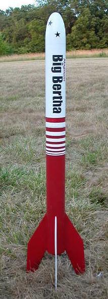
 Several layers of Rustoleum white primer was laid on and allowed to cure for a couple of days. That was then sanded heavily. The blemishes that were revealed were filled and another layer of primer was put on. That was sanded with 400 grit paper and the dust tacked off. A layer of Rustoleum Satin White was added and allowed to cure for several days. The highlight was then taped off with blue masking tape and sprayed. I must have been standing on my head when I masked off the rings, since the pattern is upside down! A logo was created using the computer, cut into masking tape by hand, then transferred to the model and sprayed using Rustoleum Flat Black. Since this “new” model is sporting a 29mm mount I decided to call it Magnum Big Bertha; that’s reflected in the new logo. A gloss coat of clear was planned, but never done.
Flying:
The weight is kind of hefty: 12oz. The original version was about 9oz. The shock cord is arranged such that the ’chute will be pulled out by the shock cord — it’s very near the eye-bolt on the lower end. The cord itself is stuffed into the upper airframe followed by the ’chute to ensure that it gets yanked out.
The first flight was with an Estes D12-3 using an Estes plastic ’chute.. I figured it wouldn’t be too spectacular of a flight since the maximum lifting weight of the D12-3 is 13oz. It’s actually a tad over. To my surprise, it was an excellent flight and went a good deal higher than I expected. Cool!
It was flown again at the club launch using an E28-4 reload and a hemispherical nylon ’chute (hand made by my young lovely). A very nice flight indeed, but the shock cord roughed up the edge of the upper section. This was smoothed out, and the inside of the tube coated with thin CA for about an inch or so. That was sanded shortly after it stopped smoking until smooth and until it fit on the coupler smoothly.
My nephew and I flew it at LDRS XXII in Argonia on an F22-5 reload. It was a bit slow off the rail and arced into the wind a bit. The delay could have been shorter, but it came out OK. More motor, is the cry! We had plans to slap an F20 in it, but were so busy with all of the things to be seen at LDRS that we simply didn’t get to it.
When the wind is cooperating we’ll give an F20-7 or an F23-7 a whirl. It should fly well on F40-7 reloads, and 24mm F21-6 Econojets, too, not to mention a variety of G’s.
This is a pretty fun model to fly. It’s good for relatively low power motors, but can accommodate some mid-power motors, too. It could handle H motors, too, ’cept it would probably never be seen again!
 |
 |
Flights
|
|