| Manufacturer: | Heavenly Hobbies  |

Presented with written permission from RocketyPlanet:
Product Review by Dr. John Smolley, MD
Wednesday, June 18, 2008
|
Bungee jumping for the fainthearted?
The new Backdraft, a BT-60 based three-foot rocket from Heavenly Hobbies, appears ordinary enough in its package, that is until you start looking for instructions. There are none. At least no written instructions. For those you need the enclosed computer CD.
Steve Shannon has commented on the issue of CD-ROM-based instructions in the Brutus review. It's one of those personal preference items like whether you want your meat near raw or well done. I liked them well enough, but like Mikey, I'll eat my steak either and any way. It is what else that is on the CD-ROM, which makes this most ordinary looking rocket, well, extraordinary.
Bundled with the usual kraft cardboard tubing, fins, chute, cone, and the like is software which helps the user to select two motors: one for the ascent and the second for the retrorocket firing. Thats right: A retrorocket firing that is timed and of sufficient impulse to stop a screaming, about to become rubbish, rocket dead in its tracks! Now if you're imagining the rocket to slow to a graceful stop, butt-end down, say like Apollo's Lunar Lander, guess again.
This is more like bungee jumping. The two motors are on either end of the rocket, nozzles pointing north and south. Rather than use electronics in a traditional dual deploy arrangement, the Backdraft goes one step further in its effort to reduce drift by allowing the rocket to arc over at apogee, come in ballistic, and then ignite the second motor at a low altitude, braking the descent sufficiently to get the laundry out safely.
Now when it comes to things like skydiving, bungee jumping, or out-of-bounds skiing, I must admit I'm a wimp. I love to watch others do it...but given a chance to let a rocket serve as proxy, sign me up. So it was with great anticipation I volunteered to do this review.
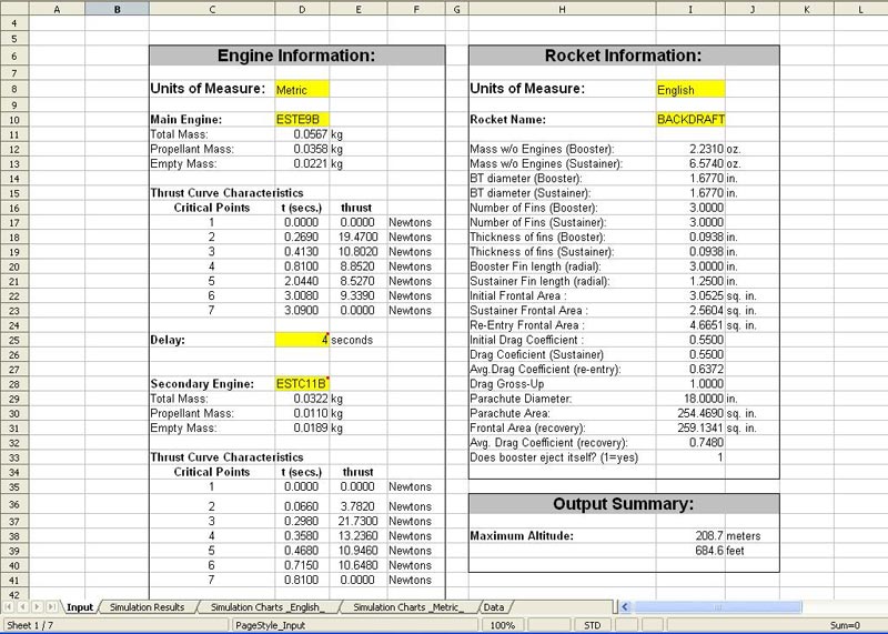
The Microsoft® Excel®-based software included with the kit allows one to compute the optimal time for the retrofire and a compatible pair of motors. Generally you need one impulse class down from the main motor-for example, recommended pairs are D12-0/C-11-0; E9-4/D12-0; E15-4/D12-3.
But the good news here is you are not limited to these motors, or even the Backdraft itself. With careful use of mass and Cd data, the simulation program works with any "nose motor" equipped rocket (or conventional rocket for that matter). With the Backdraft, the limitation on motors are twofold-the 24mm motor mounts themselves, and on the fact that the nose motor is lit by a fuse.
|
A fuse you say? For those of old-timers, this is not so shocking or outlandish. In the old days, if you wanted to airstart a motor with a delay or the stages were widely separate, this is how you did it. Of course there were failures, but I don't know that the rate was that much different than with today's advanced electronic timers/flight computers. The stock safety fuse is capable of igniting BP motors only. But with the size/motor mounts of the rocket, there really is no call for anything beyond an Estes E in the nose.
The Build:
The kit itself consists of forty parts, consisting in the main of high-quality kraft tubing, a balsa cone reminiscent of the original Big Bertha's, plywood fins, and a flat panel nylon chute. Part fit is very good to perfect, and so very little additional work was needed to assemble. Here the biggest exception was sanding the couplers.
Interestingly, for a rocket of this size, the maker recommends epoxy pretty much throughout, including the use of JB Weld or another high temp epoxy for lining the inside of the hollowed out nosecone. The cone is subject to the heat of the fuse used to delay/ignite the retro motor along with the initial blast of the motor itself. It's retained by Kevlar® line and the chute is later deployed amidship using the ejection charge of the retro motor and a piston arrangement.
|
The argument of epoxy vs. yellow glue is a horse that's been beaten to death on various forums so let's leave the flayed nag at the glue factory. Use either, but build strong and be particularly careful about selecting an adhesive that won't freeze during coupler insertions. I came very close myself to oopsing it here, even though the dry fit seemed fine. I chose to reserve epoxy for the fins, the fiberglassing, and lining the nosecone. (In retrospect, it may have been a better choice for those steps dealing with the cardboard couplers.)
As to the instructions themselves, I was confused on a couple of occasions, but overall they are quite readable and the accompanying pictures were very helpful. In total there are 24 pages, with 1 or 2 steps per page. Omitted was any mention of the launch lug, I mounted mine near the flight-ready balance point.
What would have been a nice addition (at least for the mechanically challenged like myself) would be the inclusion of an "exploded" diagram so that one has a good sense from the beginning of where all 40 parts go, and how they fit together.. But definitely, and not my habit, these are best read from top to bottom before starting the build.
What wasn't clear to me until I got my hands on the kit and software is that the booster fin can is designed to separate before the retro ever fires. If you plan on using tumble recovery, build it strong. (I used 2 layers of light FG to beef up the tube, and epoxy fillets throughout the through-the-wall construction to enhance durability.) Which comes to my next point: there is plenty of cargo room within the fin can for its own recovery.
|
So I decided to attach a high strength shock line to the fin can for two reasons. The first is that there is no reason (given you're careful in protecting the chute or streamer from the ejection gases), that the booster can't have its own recovery, and secondly by connecting it to the shock line of the top half of the rocket, one can fly this rocket in a conventional mode, leaving out the retro motor entirely. (For single motor use I would simply connect a short length of booster shock line to the cap covering the "sustainer" chute tube and untie the cap's tether. At ejection there should be enough force/momentum to pull the chute free as the booster separates. I haven't tested this, however.)
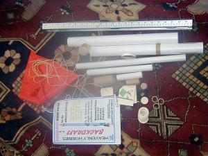
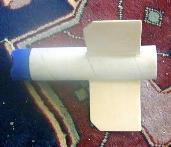
Photo 1 shows the many, many parts in this kit are of very good to excellent quality. A few differ slightly from the pics on the CD assembly, but with care, will all fit together as intended.
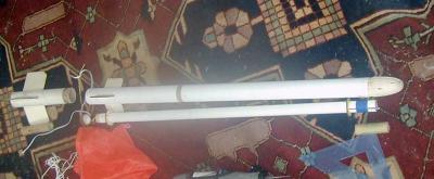
Photo 2 is a semi-exploded view of the rocket. The retro motor ejection charge is vented back toward the fins and uses a piston to eliminate the need for wadding. The chute deploys just rear of the second set of fins. A sleeved cap protects this end from the ejection charge of the primary motor.
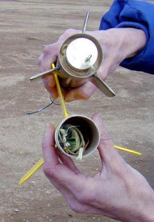
The lightly-fiberglassed fin can ready for prime coats is shown in Photo 3. This section separates from the rest of the rocket at the primary motor's ejection charge. The 95mm motor length ends at the leading edge of the fins, giving you an idea of the amount of room for a chute or streamer, versus the default tumble recovery.
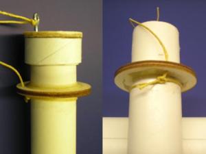
In photo 4, the left side, taken from the instructions, is of the aft end of the vent/chute compartment, showing the clever cap and tether arrangement that protects the chute from the primary ejection charge. On the right in the same photo it shows the mod I did: by drilling a small hole in the front centering ring of the fin can, I attached some of the surplus Kevlar in the same way to use as a shock cord for the booster recovery/single stage option mentioned above. Photo 5 shows the prepped rocket with streamer in place in the fincan.
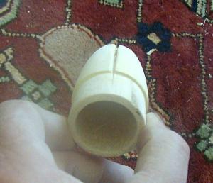
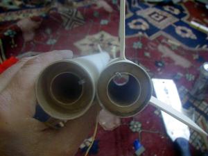
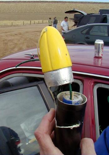
The hollow nose cone, shown in photo 6, has a groove in which the Kevlar tether is stowed during ascent. The attachment point is near the tip of the cone so it dangles along side the rocket during the retro burn. This will be lined with hi-temp epoxy to protect the fragile balsa cone from the blast of the retro motor.
|
About the Software:
I was concerned regarding the assumption that every hobbyist wanting to build this bird has access to Microsoft's Excel and Word (or even wants to). So I made sure that both the simulator and instructions were compatible with shareware that is available on the Internet. I used the Sun Microsystems Openoffice suite and was relieved to find all went well-almost that is-like Steve I had some glitches, but in the end man prevailed over machine!
First, I suspect this kit might raise a collective eyebrow in the rocket community-if not for the ingenuity of the product, from the standpoint of safety concerns. After all, what separates a ballistic core-sample recovery and a gentle, happy landing is a few inches of cannon fuse, a successful retro motor ignition, and math. Fortunately, the math is done for you in the spreadsheet: it comes with data entry for several Estes and AeroTech C-F impulse motors. By manually entering a small RASP-style data set, any motor not pre-entered can also be simulated.
Prepping the rocket begins by selecting the motors using the included simulation program:
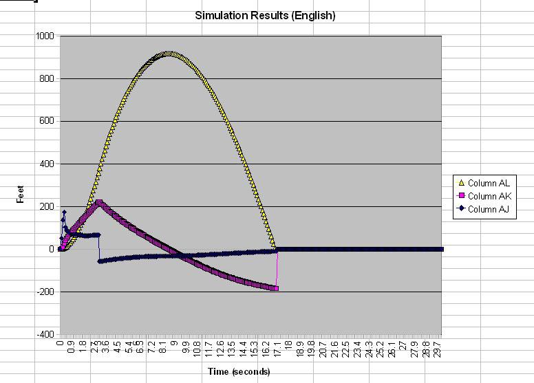
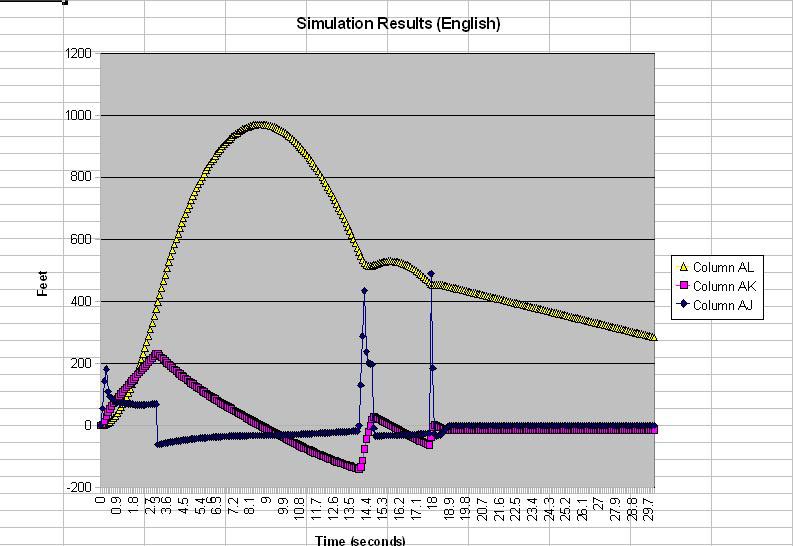
The accompanying instructions are quite clear. The first thing is to select a couple of motors and deliberately pick too long a delay. That is shown in the accompanying chart. Impact occurs at about T+17 seconds. (Yellow curve is altitude, the violet velocity, and black, acceleration).
This is the lawndart come true scenario: obviously 17 seconds is beyond the upper limit of the fuse induced delay of retro ignition.
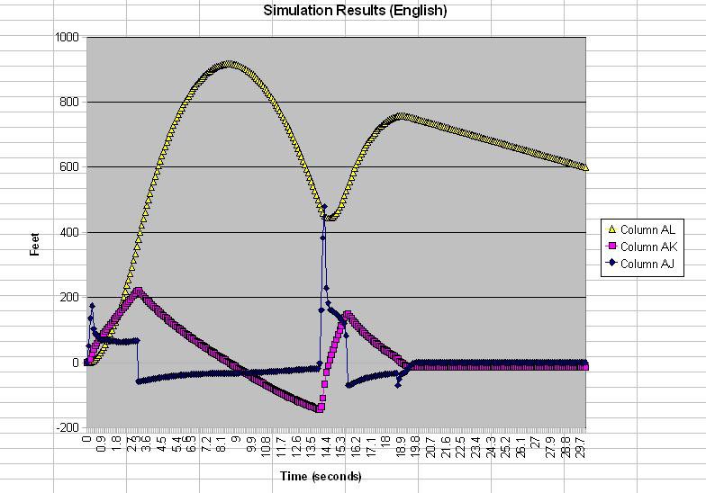
The motors used in this simulation were the Estes E9/D12 combo. The second chart reveals a situation we are also trying to avoid, that of completely overcoming the downward (negative) velocity and overshooting a near standstill to the point of a significant upward velocity.
|
As cool as the bungee bouncing/pogo-stick flight might seem, there is one small problem with this: the fins are on the wrong side of the rocket! Stability will be maintained only while there is sufficient downward velocity. An overshoot beyond this velocity would most likely lead to some harmless skywriting, but it is at least potentially unsafe and one will lose style points.
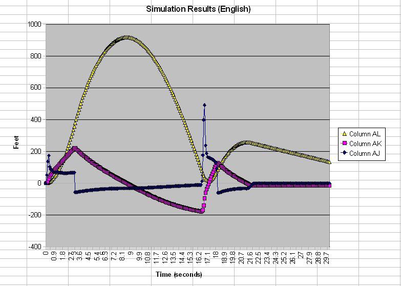
Ok, so what if we were to let it drop longer and therefore have a greater ballistic velocity to overcome. The results are shown in the next chart: while better in the sense that the peak positive velocity is not as great, this situation is also to be avoided.
Going back to the bungee metaphor, if you want your bungee long enough to plunge within three inches of the ground, first ask yourself are you really that confident, the cord won't stretch just a bit more than predicted? Same here; the software assumes perfectly vertical flights under specific conditions with exactly so much impulse. Motors vary, conditions vary, Mr. Murphy (of Murphy's Law) has been known to attend launches. So please do yourself, your friends and any spectators a favor-take heed of the designer's advice by giving yourself a significant margin of error, especially in early flights or with unflown motor combinations. Remember the line about "there are old pilots and there are bold pilots, but there aren't any old and bold pilots".
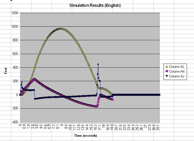
By now, it is hopefully clear that the D12 retro motor is just too big. So next step is to try a smaller impulse motor. The C11 was handy, as well as a recommended pairing, so lets give that a shot. In the next chart the improvement is readily apparent. The rocket brakes perfectly, only briefly showing any positive velocity. Lets see what can be done by shortening the delay.
Voilà! In this chart, you can see we still have the near-perfect braking and at a considerably higher altitude. Consider it cheap flight insurance.
The final screen in the series shows the H.H. Simit input screen. With the Backdraft kit, all data comes preloaded along with the advice to weigh your own rocket. Mine actually came in significantly lighter for the sustainer, and a bit lighter for the booster where I fiberglassed and added a lightweight streamer.
|
What is not shown in these plots (and by no means necessary to the concept itself) is the separation of the booster. Given the relatively small number of choices in delay lengths, there is not a lot of flexibility here-one has three choices, use a short delay for a boosted dart effect, try to separate at apogee, or carry the booster well over the top and eject during the ballistic descent. I chose to keep it simple, and chose near apogee separation. (Also, I doubt that the Simit software would model any additional kick in velocity of the "sustainer" section, if the separate-while-screaming groundward option was chosen).
Prepping and Flight:
Much of that is covered above as the most important ingredient of success here is done before you ever get to the range. Select a pair of motors that will work, and a delay that is appropriate.
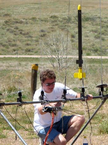
The next step which I did on the range was to measure the burn rate of the fuse. Here a stopwatch is needed and a few inches of fuse. Divide the time taken to burn into the length to get the rate. Should be something like 0.5 inches per second (about what the BATFE defines as deflagration these days ;-D) So a 14 second delay needs 7 inches of fuse. In the end I weenied out by figuring for about 12-13 seconds delay as I have enough gray hairs as is. Apart from that, sticking said fuse in a motor on the wrong end of the rocket, and stowing the Kevlar line in the nosecone groove, it's a conventional prep that went without a hitch.
The other different aspect of prepping this rocket is the need to use two igniters, one for the booster motor and the second to simultaneously light the fuse. I didn't have my big range box where I keep sundry igniters, pyrogens, and BP. So unsure of how reliably an Estes igniter would work with Visco fuse, I opted to manually light the fuse. That way I figured there would be zero chance of worst case scenario: successful primary ignition but no joy on fuse. Plus, if for whatever reason the booster motor didn't light, I'd be close and have time to yank the fuse out of the nose motor. Otherwise one ends up with a humiliating static test.
|
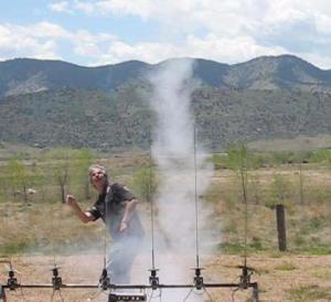
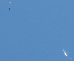
The result is shown to the left. As I'm backpedalling back from the pad after ascertaining that the fuse had burnt to the 13 second mark, the Estes E wastes no time into coming to life. The rocket wobbled some on the way up-maybe because of a high polar moment of inertia/smallish fins (dumbbell effect owing to motors on both ends)-but skyward she went with some anticipated weathercocking (another reason I weenied a bit on the delay). The booster/fincan separated just beyond apogee, and the heart stopping plunge towards Terra Firma began in earnest.
At about 300-400 feet up, my heart resumes beating when the nose motor kicks in and saves the Backdraft from certain death. That it "overshoots" a bit and does a brief mid-air thrash is easily forgiven. Few seconds later, we have the welcome sight shown in Photo 11!
Only one small fly in the ointment-the yted mine near the flight-ready balance point.
What would have been a nice addition (at least for the mechanically challenged like myself) would be the inclusion of an "exploded" diagram so that one has a good sense from the beginning of where all 40 parts go, and how they fit together.. But definitely, and not my habit, these are best read from top to bottom before starting the build.
What wasn't clear to me until I got my hands on the kit and software is that the booster fin can is designed to separate before the retro ever fires. If you plan on using tumble recovery, build it strong. (I used 2 layers of light FG to beef up the tube, and epoxy fillets throughout the through-the-wall construction to enhance durability.) Which comes to my next point: there is plenty of cargo room within the fin can for its own recovery.
|
So I decided to attach a high strength shock line to the fin can for two reasons. The first is that there is no reason (given you're careful in protecting the chute or streamer from the ejection gases), that the booster can't have its own recovery, and secondly by connecting it to the shock line of the top half of the rocket, one can fly this rocket in a conventional mode, leaving out the retro motor entirely. (For single motor use I would simply connect a short length of booster shock line to the cap covering the "sustainer" chute tube and untie the cap's tether. At ejection there should be enough force/momentum to pull the chute free as the booster separates. I haven't tested this, however.)
Photo 1 shows the many, many parts in this kit are of very good to excellent quality. A few differ slightly from the pics on the CD assembly, but with care, will all fit together as intended.
Photo 2 is a semi-exploded view of the rocket. The retro motor ejection charge is vented back toward the fins and uses a piston to eliminate the need for wadding. The chute deploys just rear of the second set of fins. A sleeved cap protects this end from the ejection charge of the primary motor.
The lightly-fiberglassed fin can ready for prime coats is shown in Photo 3. This section separates from the rest of the rocket at the primary motor's ejection charge. The 95mm motor length ends at the leading edge of the fins, giving you an idea of the amount of room for a chute or streamer, versus the default tumble recovery.
In photo 4, the left side, taken from the instructions, is of the aft end of the vent/chute compartment, showing the clever cap and tether arrangement that protects the chute from the primary ejection charge. On the right in the same photo it shows the mod I did: by drilling a small hole in the front centering ring of the fin can, I attached some of the surplus Kevlar in the same way to use as a shock cord for the booster recovery/single stage option mentioned above. Photo 5 shows the prepped rocket with streamer in place in the fincan.
The hollow nose cone, shown in photo 6, has a groove in which the Kevlar tether is stowed during ascent. The attachment point is near the tip of the cone so it dangles along side the rocket during the retro burn. This will be lined with hi-temp epoxy to protect the fragile balsa cone from the blast of the retro motor.
|
About the Software:
I was concerned regarding the assumption that every hobbyist wanting to build this bird has access to Microsoft's Excel and Word (or even wants to). So I made sure that both the simulator and instructions were compatible with shareware that is available on the Internet. I used the Sun Microsystems Openoffice suite and was relieved to find all went well-almost that is-like Steve I had some glitches, but in the end man prevailed over machine!
First, I suspect this kit might raise a collective eyebrow in the rocket community-if not for the ingenuity of the product, from the standpoint of safety concerns. After all, what separates a ballistic core-sample recovery and a gentle, happy landing is a few inches of cannon fuse, a successful retro motor ignition, and math. Fortunately, the math is done for you in the spreadsheet: it comes with data entry for several Estes and AeroTech C-F impulse motors. By manually entering a small RASP-style data set, any motor not pre-entered can also be simulated.
Prepping the rocket begins by selecting the motors using the included simulation program:
The accompanying instructions are quite clear. The first thing is to select a couple of motors and deliberately pick too long a delay. That is shown in the accompanying chart. Impact occurs at about T+17 seconds. (Yellow curve is altitude, the violet velocity, and black, acceleration).
This is the lawndart come true scenario: obviously 17 seconds is beyond the upper limit of the fuse induced delay of retro ignition.
The motors used in this simulation were the Estes E9/D12 combo. The second chart reveals a situation we are also trying to avoid, that of completely overcoming the downward (negative) velocity and overshooting a near standstill to the point of a significant upward velocity.
|
As cool as the bungee bouncing/pogo-stick flight might seem, there is one small problem with this: the fins are on the wrong side of the rocket! Stability will be maintained only while there is sufficient downward velocity. An overshoot beyond this velocity would most likely lead to some harmless skywriting, but it is at least potentially unsafe and one will lose style points.
Ok, so what if we were to let it drop longer and therefore have a greater ballistic velocity to overcome. The results are shown in the next chart: while better in the sense that the peak positive velocity is not as great, this situation is also to be avoided.
Going back to the bungee metaphor, if you want your bungee long enough to plunge within three inches of the ground, first ask yourself are you really that confident, the cord won't stretch just a bit more than predicted? Same here; the software assumes perfectly vertical flights under specific conditions with exactly so much impulse. Motors vary, conditions vary, Mr. Murphy (of Murphy's Law) has been known to attend launches. So please do yourself, your friends and any spectators a favor-take heed of the designer's advice by giving yourself a significant margin of error, especially in early flights or with unflown motor combinations. Remember the line about "there are old pilots and there are bold pilots, but there aren't any old and bold pilots".
By now, it is hopefully clear that the D12 retro motor is just too big. So next step is to try a smaller impulse motor. The C11 was handy, as well as a recommended pairing, so lets give that a shot. In the next chart the improvement is readily apparent. The rocket brakes perfectly, only briefly showing any positive velocity. Lets see what can be done by shortening the delay.
Voilà! In this chart, you can see we still have the near-perfect braking and at a considerably higher altitude. Consider it cheap flight insurance.
The final screen in the series shows the H.H. Simit input screen. With the Backdraft kit, all data comes preloaded along with the advice to weigh your own rocket. Mine actually came in significantly lighter for the sustainer, and a bit lighter for the booster where I fiberglassed and added a lightweight streamer.
|
What is not shown in these plots (and by no means necessary to the concept itself) is the separation of the booster. Given the relatively small number of choices in delay lengths, there is not a lot of flexibility here-one has three choices, use a short delay for a boosted dart effect, try to separate at apogee, or carry the booster well over the top and eject during the ballistic descent. I chose to keep it simple, and chose near apogee separation. (Also, I doubt that the Simit software would model any additional kick in velocity of the "sustainer" section, if the separate-while-screaming groundward option was chosen).
Prepping and Flight:
Much of that is covered above as the most important ingredient of success here is done before you ever get to the range. Select a pair of motors that will work, and a delay that is appropriate.
The next step which I did on the range was to measure the burn rate of the fuse. Here a stopwatch is needed and a few inches of fuse. Divide the time taken to burn into the length to get the rate. Should be something like 0.5 inches per second (about what the BATFE defines as deflagration these days ;-D) So a 14 second delay needs 7 inches of fuse. In the end I weenied out by figuring for about 12-13 seconds delay as I have enough gray hairs as is. Apart from that, sticking said fuse in a motor on the wrong end of the rocket, and stowing the Kevlar line in the nosecone groove, it's a conventional prep that went without a hitch.
The other different aspect of prepping this rocket is the need to use two igniters, one for the booster motor and the second to simultaneously light the fuse. I didn't have my big range box where I keep sundry igniters, pyrogens, and BP. So unsure of how reliably an Estes igniter would work with Visco fuse, I opted to manually light the fuse. That way I figured there would be zero chance of worst case scenario: successful primary ignition but no joy on fuse. Plus, if for whatever reason the booster motor didn't light, I'd be close and have time to yank the fuse out of the nose motor. Otherwise one ends up with a humiliating static test.
|
The result is shown to the left. As I'm backpedalling back from the pad after ascertaining that the fuse had burnt to the 13 second mark, the Estes E wastes no time into coming to life. The rocket wobbled some on the way up-maybe because of a high polar moment of inertia/smallish fins (dumbbell effect owing to motors on both ends)-but skyward she went with some anticipated weathercocking (another reason I weenied a bit on the delay). The booster/fincan separated just beyond apogee, and the heart stopping plunge towards Terra Firma began in earnest.
At about 300-400 feet up, my heart resumes beating when the nose motor kicks in and saves the Backdraft from certain death. That it "overshoots" a bit and does a brief mid-air thrash is easily forgiven. Few seconds later, we have the welcome sight shown in Photo 11!
Only one small fly in the ointment-the yellow nose which should be dangling along side the rocket is nowhere to be seen. The clue as to why is here in this review, winners receive a years free subscription to Rocketry Planet.
Discussion:
I suspect that this rocket might generate some controversy. I know it raised differences of opinion among the Rocketry Planet moderators who act as RSO's.
|
Is this rocket sufficiently safe to fly? In trying to answer this, I looked at all the relevant safety codes and could find no reason to disqualify the rocket. Maybe on account of the fact I'm an old-timer, who has used real honest to God mercury switch/capacitor fired/flashbulb cannon fuse for airstarting BP motors, and seen it work, I wasn't as skeptical as some. No I have never flown a retro rocket before, but in the end, the relevant question is: does this rocket present that much greater a hazard than others we fly?
Bottom line, I say, no. Sure it would be great and likely safer to electronically perform the same task. No different than deploying the main at 500', one should at least be able to ignite the retro at x altitude, or ideally x feet per second. But this is about adding a new twist to mid-power fliers who cannot or choose not to splurge for electronics. I would treat this rocket just as C.R.A.S.H. did-a heads-up flight, with an additional element of fire risk.
As packaged, I'd say it makes the short list of all the under-F powered kits that truly were in one sense or another, revolutionary. If I had to prune that list to say six, they would include the Estes Astron Spaceplane (boostglider), the Estes Gyroc (helicopter recovery), the Centuri Hustler/Lil Hustler (designed for BP F engines), the first multiengined rocket/s (not certain these are right - Estes Apogee (staged) and Ranger(cluster)), the AeroTech Phoenix R/C rocket glider, and the Backdraft. Thats pretty select company.
I picked those because each of these rockets opened up a new vista in sport rocketry, and yet none were particularly aesthetically appealing rockets. The Backdraft fits this bill entirely. It's certainly not about to turn heads sitting near your field box, in fact it's a tad homely. But as the rocket barrels in destined for certain destruction, just then, the nose motor kicks in, gracefully braking the banshee-like descent, and a few seconds later, gently floating under chute, she will most definitely turn heads when flown. One can immediately think of all kinds of interesting competitions based on the concept, and roaming into the domain of high power and extreme rocketry, maybe some applications there as well.
I strongly recommend the kit based on high KEWL factor, innovation, and overall quality. And a definite strong thumbs up goes to Jose Andrade-Cora, the designer and proprietor of Heavenly Hobbies.
Retro Rocket/Backdraft Background:
Jose provided me with a memo he had written previously about the inspiration and development of the Backdraft:
Back in 2002, as our family vacation loomed near, I placed an order for some NARTS publications to provide some relief from the "packaged" distractions found in the big Florida theme parks. Among the assorted reports and technical papers, there was one that seriously caught my attention. It was a NARAM-34 report by Bruce Markielewski about construction of what he termed "retro-rockets". These models were rockets that bypassed ejection at apogee for a delayed deployment of their recovery system. To counteract the gravity force during re-entry, a second engine was fired. This second engine would slow down the rocket sufficiently for the recovery system to take over. I thought that "retro-rockets" were a great idea, as they added complexity and interest to the usual rocket flight patterns that, frankly, were getting old.
Markielewski's stated objective was to "...design and build a reliable, functioning model rocket using a 'retro-rocket' technique to slow the descent of the model rocket before deploying a parachute or other recovery device." This objective, however interesting, failed to focus on the possibility of using the "retro-rocket" concept to reduce the drift of the model from the launching pad. Common Dual Deployment™ techniques use electronic actuators to force the ejection of a streamer or small "drogue" parachute to cause a fast, but controlled, descent. A larger parachute is subsequently deployed by similar means. The idea is to reduce the time the rocket is subject to crosswind drag, therefore reducing the drift.
However, a rocket using the "retro" techniques does not "break up" to deploy a recovery device in its coasting phase after apogee. It, therefore, presents a smaller frontal area to crosswinds. Less frontal area means less drag and less drift. Also, crosswinds acting on parachutes create lift forces, so not having a parachute in this phase of the descent also helps. Moreover, a compact rocket presents a much more aerodynamic profile in the vertical direction, allowing higher (more negative) terminal velocity limits. This leads to much reduced periods during which the model rocket is subject to crosswinds, and again, less drift. In simple words, the "retro-rocket" technique is superior to the common Dual Deployment technique in reducing crosswind drift.
To put Markielewski's work in perspective, one must realize that to achieve his objectives, a fair amount of mathematical calculations were required, perhaps too many or too intensive for the average modeler. However, I realized right then and there that the limitations that were real in 1992 were no longer there in 2004. The personal computer had removed them from the picture! In other words, I had found an alternative for Dual Deployment which, provided the rocketeer had a computer at home, didn't require expensive electronics or demanding mathematical calculations, rendering it attainable to many more rocketeers. This was the birth of the TailWind delayed-deployment system.
Soon after my vacation was over, I started working on the first prototype for my version of the "retro-rocket". It was a single-stage, large diameter rocket with ducted ejection gases for rear ejection. That design never took to the skies. To my knowledge, the available software was not able to model the unusual shapes and flight paths that I was conceiving. I had realized that the controlling software was even more essential than the rocket itself. My top priority then became to develop the software that would take the place of the deployment electronics. The software was essentially a simulation program, optimized for the Backdraft model. It obviously had to take into consideration gravity, thrust and drag, but it also had to give due weight to the unusual changes in physical characteristics that would occur during flight. This work eventually became the H.H. Simit simulation software.
H.H. Simit (v1) is included in all new Backdraft kits. It provides simulated altitude, velocity and acceleration information for the model's flight. It also allows the flyer to easily choose primary and secondary engines (and their respective delays) using the provided data. These choices are critical for the safe flying of the model. Future rocket or engine modifications will not be a problem as the information database is user-editable. You don't need to buy a new version of H.H. Simit to fly a new version of Backdraft or to accommodate the thrust characteristics of a new engine! As development continues, H.H. Simit will be made available as a separate product.
Subsequent prototypes abandoned the large-diameter airframe for a more energy-efficient BT-60 based design. The final design offers a booster-style detachable propulsion module, straight-through ejection gas ducting and EZject piston-actuated system for rear ejection. With the EZject system, flameproof wadding and / or parachute protectors are completely unnecessary, making field preparation a breeze! EZject is different from other piston-based ejection systems in that its simplicity and low manufacturing cost makes it available to all rocket designs, even the most simple and basic (see the Heavenly Hobbies' Stratos-13 ELM and Stratos-18 ELM models).
The essential physical difference between the Backdraft and a common 2-stage rocket is that the second-stage engine has exchanged places with the recovery system. The secondary engine been moved forward, behind the nosecone, while the parachute has moved back. This secondary engine has also been rotated 180°, so that the nozzle points to the sky while the rocket sits at the launch pad. As I said before, when lit, this engine will provide thrust to counteract the force of gravity and slow down the rocket sufficiently, so that the parachute can open without tearing to shreds. Since the parachute can open as close to the ground as desired, drift is reduced considerably. The reduction in drift allows the hobbyist to fly higher and/or in windier conditions. This is the magic of the TailWind delayed deployment system.
Since the secondary engine is far removed from the primary engine, the primary engine cannot be used to directly ignite the secondary one. This problem would normally be remedied with an electronic timer or other similar artifact. However, it was a design objective for the Backdraft to "kick it old school" and avoid any electronic control artifacts inside the rocket. As a result, a good old visco fuse ("cannon fuse") is used to delay the firing of the secondary engine. This fuse is lighted at the same time as the igniter for the secondary engine, so a good 12-volt launch system is needed. You also need to time your fuse accurately, so a stopwatch will come in handy also.
It is critical to follow the instructions in building and flying this model. I have gone through several prototypes in perfecting a safe and reliable flying procedure, so you don't have to! Use H.H. Simit to your advantage, and remember to allow yourself a margin of error in your calculations.
Happy flying!
Jose M. Andrade-Cora
Heavenly Hobbies LLC
Now in fairness, this idea goes back at least as far as the 1970's when it was discussed in a rocketry magazine article. The first large public launch was at NARAM 1992, where Bruce M. staged a test flight in conjunction with his R/D report. Many have tried more or less the same approach with varying degrees of success both before and since, but never to my knowledge with quite this level of sophistication, and certainly not in a kit with integrated software.
It was something of an honor for me to fly this at a C.R.A.S.H. launch. After all, this was Bruce M.'s old club and launch site. Sadly, Bruce passes a few years back. His legacy certainly lives on, and the Backdraft a fitting piece of such. I am sure Bruce smiled from beyond the Saturday my Backdraft flight took place.
Other Reviews
- Heavenly Hobbies Backdraft By Nick Esselman (November 13, 2010)
I purchased the Heavenly Hobbies Backdraft because it sounded really different. The site says " The exciting Heavenly Hobbies’ BACKDRAFT is a dual-engine rocket... ". Notice is said dual-engine, not cluster. It then went on to describe the rocket this way: " The BACKDRAFT looks like a 2-stage vehicle, with booster and sustainer sections. The propulsion module (booster) holds the primary ...
- Heavenly Hobbies Backdraft By Dick Stafford (August 2, 2008)
The Backdraft is a BT-60-based, 24mm-powered rocket that on face value looks like a standard 2-stager. If you've read the previous reviews (and I assume you will before you continue past this intro), you'll know that there is one major difference--the upper motor is used as a retro rocket. Heavenly Hobbies calls this the TailWind delayed deployment system. The upper stage is ignited with a ...
 |
 |
Flights
|
|
J.S. (June 25, 2008)
|
|
C.S. (June 25, 2008)