LOC/Precision Bruiser EXP-3 Original Design / Scratch Built
LOC/Precision - Bruiser EXP-3 {Kit}
Contributed by Stephen Krall
| Manufacturer: | LOC/Precision  |
Note: This is a slightly condensed version of all the information that Stephen has produced for his Level 3 project. Visit his homepage to read the additional information and enjoy additional pictures.
 Introduction:
Ever since my Estees days I seemed driven to build the next project a little bit bigger than the last one, and of course to do that you need a bigger motor :-) hee hee. After completing my Level 2 project with a successful flight in March of '99 I was a happy camper. At that same launch I witnessed my first "M" flight by Jim Scarpine and his Beautiful Star Leopard Rocket, and then it happened, I was bitten by the Level 3 bug. I knew after that launch was over that I had to build a bigger rocket with a bigger motor. A big rocket that would go at least a mile high plus. So at this web page you will see how I progress as I build my Big Rocket with a Big motor.
ROCKET REVIEW:
Jim Livingston and Mark Lloyd have agreed to be my TAP reviewers for this project. I met Jim at Whitakers, NC while making a successful Level 2 attempt, and I have flown with him several times since then. I have flown with mark now several times and both him and Jim have seen the project up close and personal at Spring Weld. At this time my Level 3 attempt will be made at Whitakers, NC on June, 17 2000. Whitakers, NC has well over 1000 sq. acres of Cow pasture with surrounding fields of low crop land of equal size. Altitude attempt will be one mile.
GENERAL:
This is an online version of the Tripoli Pre-flight Review Checklist Which is required before the launch of this Level 3 project. The Data Capture form is included in the web site and Photos of construction process will also be documented. All material will be printed out and submitted to the TAP members reviewing this project.
AIRFRAME:
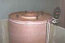
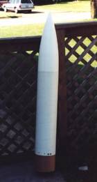
The Airframe will be constructed out of Loc/Precision 7.67 tubing and is in fact their Bruiser EXP 3" kit with modifications to make it a level 3 Project. It will reinforced on the inside by using Concrete tubing acting as a double wall with a total thickness of 1/2 inch, where ever the tubing is not reinforced by other means such as a motor mount and electronics bays, and nose cone. The fins are made of G-10 fiberglass and are attached to the motor mount using West Systems Epoxy and 9 oz fiberglass tape . All adhesive used on this project are from the West Systems Product line and the filler used is 406 Cellulose and 404 high density. The Nose cone is Loc/Precision Plastic molded nose cone. This is a single stage rocket, no clustering is involved in the project.
Safety is an extremely important part of airframe construction. A shred could cause property and bodily damage to all with in the launch area. This rocker is being built with a design and materials proven in the High power rocket community.
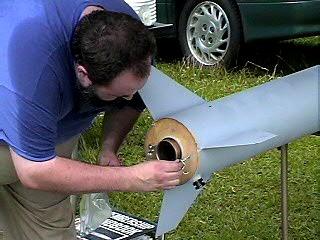
FINS MOTOR MOUNT:
The basic design of the motor mount is the "Tube with in a Tube" (TWT) design which comes with the Loc Bruiser EXP 3" plus additional modifications to handle an "M" class motor. Below you will see the process of construction with an explanation for each process.
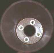
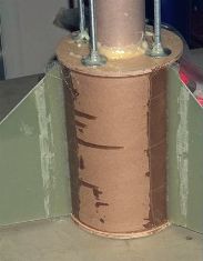
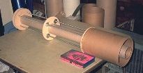 In Photos 1 and 2 you can see the TWT design. I added 3/8" steel rods for support from the 2 centering ring all the way up through the bulkhead plate. |
|
 In this photo you can see that I gave extra support to the TWT design by using 3/4 dowels long the outer tube and the motor tube. |
|
|
 |
|
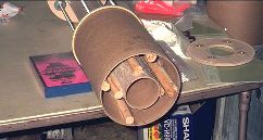
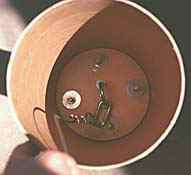
| The 5th photo shows the motor Mount mostly completed with a few minor touch ups left to do. In Photo #6 you can see how the fins are attached. I have used 9 oz fiber glass tape as a fillet to attach the fins to the inner tube. I will use epoxy fillets with filler (#406 West systems) on the outside of the main airframe.
The motor mount will be partly constructed inside the booster section of the rocket. Before it is inserted into the booster section the bulkhead plate and top centering ring will be removed. This will allow epoxy to be poured down onto the third centering. Once the epoxy has cured the fourth centering ring will be installed and epoxied. Then the bulkhead plate will be installed and epoxied into place. The rear centering ring will also be epoxied in a 1/4 from the rear edge of the airframe. |
||
BOOSTER:
 |
 |
 |
| After fins slots were cut into the main body tube the motor mount was inserted into motor tube. I then used rope and old motor in a tourniquet type application to tighten the air frame around the rear centering ring. I inserted screws into the four t-nuts to keep epoxy out the inserts. I then poured enough epoxy to fully cover the rear centering ring. Each screw was then turned one turn every half hour so as not be be epoxied in place. | Prior to inserting the motor mount into the booster section it was disassembled, removing the 3rd, 4th centering rings, and bulkhead plate. Once the mount was epoxied in the booster section the at the rear centering the motor mount was re-assembled inside the booster section epoxying each centering ring and bulkhead consecutively. |
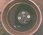
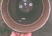
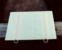
In this photo you can see the Bulkhead plate installed prior to being epoxied in place. You can also see part of the recovery system hardware. Below you can see the 3/16 wire rope used as a connection point for the shock cord. |
 |
 |
 |
 |
||
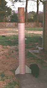
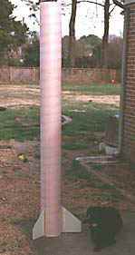
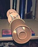
| I decided I did not want to fiberglass the Booster section, but I did decide to double wall the booster section from the top of the bulkhead on the motor mount to 6 inches below the top of the section. This is to allow the payload coupler to sit properly in the booster section. I used concrete form tube as a double wall. It was cut down to fit snugly into the booster section. Here you can see it as it was epoxied into the booster section. | In this photo you can see the additional 24 inch Airframe that I added to the booster section. The booster section now stands 7 feet tall. I added the additional airframe to increase the size and weight of the rocket which will reduce altitude. Oh, by the way in case you are wondering, that black blob next the the rocket is my dog Emmett. He loves going to a launch, but hates the noise. | In the above photos you can see second wall installed into the booster section. With the exceptions of the fin fillets the booster section is complete and ready to go. |
RECOVERY SYSTEM:
The recovery system will comprised of U-bolts, and quick links with 1100lb rating. The U-bolts will be installed into 1/2" Birch bulkheads. The Rocket will split into three separate pieces during the decent and all sections will be attached by a shock cord consisting of 1" Tubular Nylon. All ends of the shock cord will be attached directly to the bulkhead ubolts by Quick link with the exception of the Booster section connection. A Steel cable will be installed into the booster section attaching to the top bulkhead plate ubolts in the motor mount. The cable will run up the booster section to just below top of the booster section where a loop will be made in the cable. A quick link will then be attached to the loop in the end of the steel cable. The drogue chute will consist of a 24 " chute made by Rocketman. The main chute will consist of a R14 Rocketman chute .
Safety is an extremely important part of a recovery system. A failure in the recovery system could cause property and bodily damage to all with in the launch area. The Recovery system is using tested and rated parts and each bulkhead is bolted to the rocket using steel rods.
AVIONICS DESCRIPTION:
The electronics will consist of dual RRC2 Missile Works Altimeters. I have used this altimeter on many flights with flawless operation. These altimeters are dual deployment altimeters and will deploy the drogue chute at apogee and the main chute at a selected altitude(800 ft). Each altimeter will have its own power source (9 volt battery). Both Altimeters will be mounted on a piece of G-10 fiberglass in the electronics bay. The board will slide into the electronics bay on two of the steel rods used for support and bolted in to place. The switches will be two key switches that snap into the "on Position" All switches will be activated from the outside of the rocket. Continuity of ejection charges will be indicated by three audible beeps from each altimeter.
Each altimeter will have its own Electric match (Davey Fire 28F) going to a single charge at each stage of the deployment. I believe that if the charges used to separate the rocket sections are properly tested on the ground then there should not be a need for a secondary charge at each stage of the deployment. Redundant charges could lead to the destruction of the rocket or recovery systems. If you have two separate altimeters with there own power source then one of those altimeters will light a single charge. If they don't then a secondary charge really isn't necessary.
Safety is an extremely important part of a electronics system. I consider this the most important part of the rocket as far as safety is concerned. I don't believe that any other possible failure could be as disastrous and cause the greatest injury then the failure of the electronics system which could result in a rocket returning to earth ballistic.
 |
 |
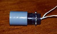 |
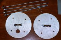
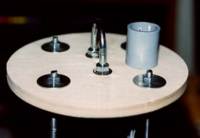
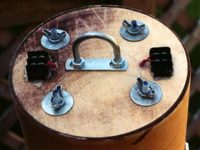
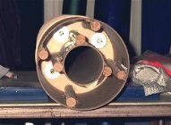
| These are the basic parts for the electronics bay. I used 1/4" threaded rods. I replaced the original bulkhead with nice half inch bulkhead for extra strength. U-bolts are 1" in size. The Coupler (not shown) is double walled. | In this photo you can see the forward assembly of the electronics bay. The cup on top is a removable Ejection charge holder. I use a removable ejection charge holder so I could permanently install the forward Bulkhead of the electronic bay. | This is the removable ejection charge holder. It is made out of a female to female PVC connector and a threaded PVC connector. The threaded connector is cut to length to fit onto the 1/2" bulkhead. An O ring (not Shown) will be placed between the cup and the bulkhead to seal the bay from the ejection charge gases. |
 |
 |
 |
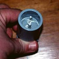
| In the cup I will have two davey fire matches attached to different altimeters. The cup will hold up to 11 grams of power. I will only be using 6.5 grams to remove the nose cone during flight. | Here you can see the inside of the electronics bay. I tried to keep it simple. | This is the electronics board. Two RRC altimeters will be mounted on this board side by side and they will slide into the bay as shown in the last photo. |
 |
 |
 |
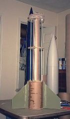
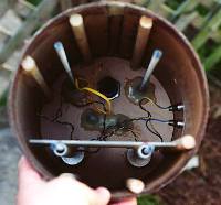
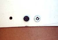
| This is the aft end of the electronics bay. I have mounted two terminal blocks on the bulkhead. Each block will be connected to one altimeter. One match will run from each block to a single large charge, appox 10 grams, to separate the payload section from the booster. As you can see I have already tested it and it worked great. | I decided to use key switches to arm the altimeters. This seem to be the best method of arming the electronics. These are sturdy switch which snap into the "on" Position. They are much easier to install than the DPDT switches which were my first choice. | Here is the entire payload section. It stand 4 ft 10 inches |
 MOTOR:
The Motor used to launch this project will be a Kosdon M1130 which is a Tripoli Certified. A B&K igniter will be used to ignite the motor.
This Motor is a pre manufactured motor made by a well know motor manufacture. It has a long track record for being a reliable and safe motor. The possible failure would come from incorrect assembly procedure which would result in a cato. If the safety distances set by Tripoli are observed and a cato does occur then injury or damage to others should not be a problem.
LAUNCHER:
The Rocket will be launched using a rail 12 feet long on a heavy duty launch pad. It will be launched straight up and will need no other launch support. The rocket will weight approx. 46 lb full loaded.
PERFORMANCE:
The basic rocket design is that of a Loc Bruiser EXP 3" kit with modifications made to it to reinforce the structure to handle an "M" motor. Length was added to add weight and stability to the rocket, and to keep altitude down to make it more manageable for launch site. Rocket simulation was done with Wrasp.
OPERATIONS:
In Accordance with the TAP Pre-Flight Review, the following pre-flight checklist has been prepared.
- Assemble Electronics bay, installing new batteries in the altimeters and testing the altimeters.
- Assemble 2 ejection charges. ( Apogee 10.0gr. Main 7.0gr)
- Assemble Main chute and attach Recovery harness for payload section.
- Assemble Drogue chute and attach recovery harness in for booster section and assemble rocket.
- Assemble the Kosdon M 1130 Motor and install it into the rocket and secure with retaining brackets.
 Load rocket onto the Launcher.
- Arm altimeters, Power will switched on by a key switch and continuity will be verified by three audible beeps from each altimeter.
- Install igniter and connect to launch control system and verify continuity.
- Say a prayer on the way back to the flight line to await launch.
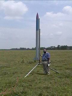
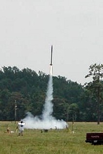
SUCCESSFUL LEVEL 3 FLIGHT!
June 17, 2000
Witakers, NC
Rocket - Modified LOC Bruiser-EXP 3"
Weight - 44 lbs
Motor - Kosdon M1130
Altitude 5955 Feet
The rocket had two additional successful flights. One on another Kosdon M1130, but I can't remember what date it was. It also flew on a Kosdon M2240 on the very last day that Kosdon motors were legal. I shredded the rocket at the spring WELD launch 2002 (Whitakers Experimental Launch Days) using a motor of my own design.
Thanks goes out to everyone who helped me make this a successful flight. Thank you for your support and encouragement.
 |
 |
Flights
|
|