| Construction Rating: | starstarstarstarstar_border |
| Flight Rating: | starstarstarstarstar |
| Overall Rating: | starstarstarstarstar_border |
| Manufacturer: | LOC/Precision  |
Brief:
The LOC/Precision EB-3.90L is a electronics bay for use with 4" diameter
paper tubing. This design comes from LOC in 4 different diameters (3.00",
3.90", 5.38", and 7.51") as well as extended lengths in the
3.00" and 3.90" (designated with an 'L' at the end of the part
number). This review only covers the 3.90" extended version but assembly
and usage of the other sizes/lengths should be identical.
Construction:
I was looking for a simple and complete solution (minus the altimeter of
course) to convert at least one of the HPR rockets in my fleet to dual deploy.
While not at least in my opinion a complete solution, the LOC electronics bay
is as close as you can find out there today.
Here is what comes in the kit:
- 1 8" long 3.9" diameter coupler
- 1 7.5" long Stiffy coupler
- 1 1" long 3.9" diameter airframe tubing
- 2 coupler bulkheads (1/4" birch plywood)
- 2 9" long 1/4" diameter threaded rods
- 2 eyebolts
- 4 fender washers
- 7 1/4"-20 nuts
- 2 1/4" lock nuts
- 4 metal washers
- 2 nylon washers
- 2 wing nuts
- 3 6" long 1/4" paper launch lugs (tubing)
- 1 pre-marked 2" x 5.5" x 1/8" birch plywood
Here is what is needed to complete the bay:
- Altimeter (not including this is a good thing as there are many out there and they all vary in cost, ease of use, and functionality)
- Arming switch (again, a matter of personal preference)
- Terminal blocks for attaching electric matches
- Nuts, bolts, and spacers for mounting altimeter
- Holes drilled in bulkheads for routing wires from altimeter to terminal blocks
- Holes drilled in couplers for mounting arming switch and vent(s) for barometric sensors
- Wiring for connecting altimeter to switch and terminal blocks
- Ejection canisters
Assembling the electronics bay (at least as far as LOC's instructions walk you through) is fairly easy and did not take very long to complete. Speaking of the instructions, They came on one sheet of 8.5" x 11" paper printed on both sides. The only pictures or diagrams was a single computer drawn "exploded view" of the bay. The instructions follow a logical order but could really benefit from a diagram or picture to accompany each of the 4 major steps of the build.
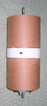
The first part was to glue or epoxy the three large tubes together. The Stiffy coupler (a nearly 1/8" thick paper coupler is centered inside the large coupler tube to provide overall strength to the design as well as provide a seal and shelf for the bulkhead to rest against. The one inch ring of tubing is then centered on the outside of the main coupler.
Next was attaching the eyebolts onto the bulkheads. Something I didn't quite understand here is that these holes were 1/2" diameter when only 1/4" diameter bolts were going through them. Fender washers cover these holes completely though. Firmly tightening all of the nuts and then epoxying the threads ensure that nothing will come loose in the future. And although not mentioned in the instructions, aligning the eyebolts perpendicular to the holes for the threaded rods will ensure that you don't have any problems with the remainder of the assembly and especially when it comes to loosening/tightening the wing nuts to prepare the bay for flight.
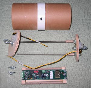
Third step is to assemble the hardware onto the threaded rods. Two 7/16" wrenches are needed here so that you can wrangle the lock nuts onto each rod. Washers, one of the bulkheads, standard nuts, and dabs of epoxy complete the rods.
The final build step is to build the altimeter sled by sliding two of the paper lug tubes onto the threaded rods. The lines on the plywood should rest right on the tubes and show right where glue needs to be applied. (I also roughed up the tubes with 150 grit sandpaper so that there would be plenty of bite.) I centered the wood in the middle of the paper tubes so that it cannot hit the ends of the eyebolts. I added some small fillets to be on the safe side as well. Lastly, I took the third paper tube and cut ~1.25" long pieces off and slid them onto the threaded rods so that the sled will not slide inside the bay during flight. (This is not mentioned in the instructions as the documentation appears to be used for all diameter and lengths of LOC electronics bays. I would have to make a reasonably educated guess that the standard length bays would not come with this third piece of tubing.)
It is also worth noting that I have a MissileWorks RRC2 that used with this bay. The mounting holes in the altimeter are near the corners of the 6" long altimeter--too far apart to mount all four corners onto the sled. I cut a couple strips of 1/8" birch ply to glue onto the ends of the sled so that I could attach the RRC2 properly. By gluing these strips on the opposite side of the sled, I also afforded myself a way to mount another (shorter) altimeter or a timer for alternate or redundant uses.
Then I was still left to mount the altimeter and do the wiring. The altimeter was mounted to the sled with 4 stainless #4-40 x 1" bolts, nylon washers (to eliminate any accidental grounding issues), steel washers, and stainless steel nuts. The wiring is 20 gauge paired wire. Wires were permanently installed to connect to terminal blocks screwed into the outside of both bulkheads and to the slider switch. I used a hot glue gun to seal off the wiring in the bulkheads to prevent any of the ejection charge from unwantedly entering the electronics bay. The switch is a simple slider that is mounted radially inside so that any rapid changes in the rocket's intertia will not cause the switch to change positions. I shaved off some of the switch with my Dremel so that it does not extend outside the airframe and power off or on without some form of human interaction as well. I fabricated a small wood bracket to mount the switch securely inside the bay. In an effort to prevent any mishaps at the field when connecting the wires, I also printed and taped some small labels for each of the 3 pairs of wires to identify the switch, main chute, and drogue chute.
PROs: Heavy duty design, easy to build.
CONs: Instructions on the sparse side, builder is still left to buy and install the wiring, sled may not be long enough or require some modification for some altimeters.
Finishing:
I was still left with all of the wiring to do. I scoured the internet for as
many websites and pictures of electronics bays as well as looking at the bays
of the rockets of experienced members of my club who regularly fly dual deploy
configurations. Visits to the local home improvement and electronics surplus
stores in town had me with all of the remaining parts I needed.
There is only one small piece that even need to be considered for painting--the 1" wide piece of tubing where the vent hole(s) and switch are located. I gave mine a coat of Krylon white primer before laying down the Krylon gloss white.
Construction Rating: 4 out of 5
Flight:
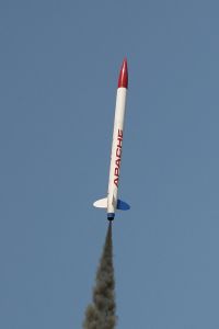
I modified my BSD Apache by removing the payload section and replacing it with
a 17" long piece of LOC 4" body tube, a shock cord from another high
power rocket in my fleet, and the electronics bay to join the rocket together
in the middle. I borrowed the 14" LOC chute from my Weasel for a drogue
and a Top Flite 36" chute that I use for many of my larger rockets in my
fleet. The rocket was loaded up with a Pro38 H143SS. I wanted a motor that
would keep the rocket visible for the entire flight. I was quite excited to see
my first dual deploy flight!
The smokey motor ignited instantly and boosted the rocket into the calm sky. The rocket stayed easily in view during the entire flight.
Recovery:
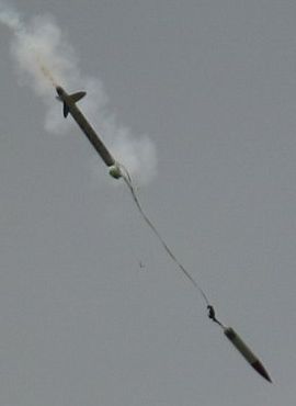
The Apache arched over at apogee and the Missile Works RRC2 fired the primary
charge releasing the drogue chute. Just a few short seconds later the main
charge fired to release the 36" chute. The rocket drifted down at a
comfortable rate and landed a little too close to where it lifted off from--we
have the pads on a patch of asphalt and the Apache landed on the paved surface
(less than 50ft away from the pad) with the motor casing taking the brunt of
the impact for the booster, the tip of the nose nose striking first for the
upper section and the electronics bay hitting on its edge. All of the damage
was only cosmetic and the altimeter clearly beeped out 760 feet. The flight was
quite low but the goal was accomplished perfectly!
 Post-flight insepction also revealed that I perhaps had used a
little too much BP in the PVC caps. I know there are many folks who subscribe
to the "Blow it out or blow it up" philosophy but I'll be more
careful next time when prepping it for flight. I'd prefer to subscribe to the
"Just enough. Really." school of thought...
Post-flight insepction also revealed that I perhaps had used a
little too much BP in the PVC caps. I know there are many folks who subscribe
to the "Blow it out or blow it up" philosophy but I'll be more
careful next time when prepping it for flight. I'd prefer to subscribe to the
"Just enough. Really." school of thought...
Summary:
Either as part of a kit (all of the LOC/Precision HyperLOC series and any LOC
kit that has the Multi-Chute Deployment (MCD) option) or retro fit onto an
existing kit, the LOC Electronics Bay is fantastic for the newbies and
experienced flyers using electronics in their rockets. With the specifics of
wiring left out, it allows the builder to customize it to his needs. It is
exceptionally durable and fits common paper tubing commonly used for rocket
building.
Overall Rating: 4 out of 5
 |
 |