MD 4 Inch Level 3
By Mark H
2014-02-26
Preliminary Design
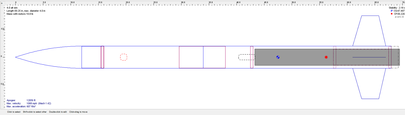
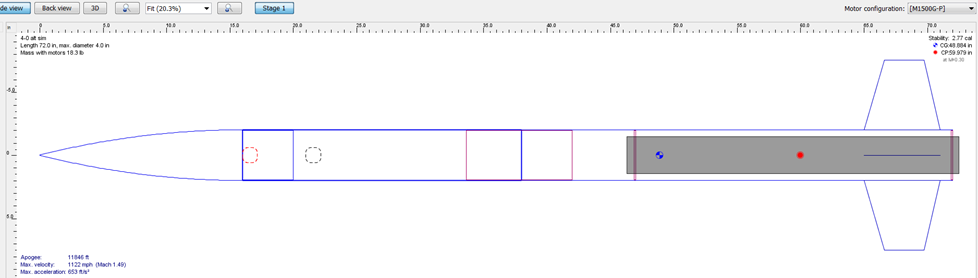
This rocket will be a 4 inch 4 fin minimum diameter rocket built for L3 certification. A 98/75 mm adapter will be used to fly 75 mm motors, as shown.
Fins
2014-03-01
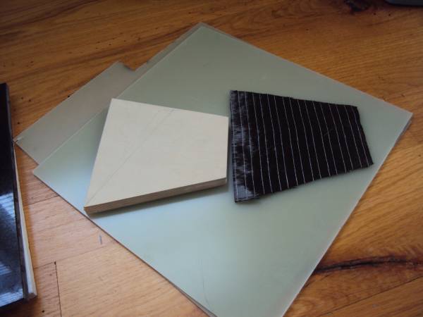
The fins were cut from 1/8 inch 5 ply Baltic Birch. The fin span is 5.5 inches, with a 6 inch root. Here I have match sanded the fins using a sanding block. The fins are taped together using double sided carpet tape.

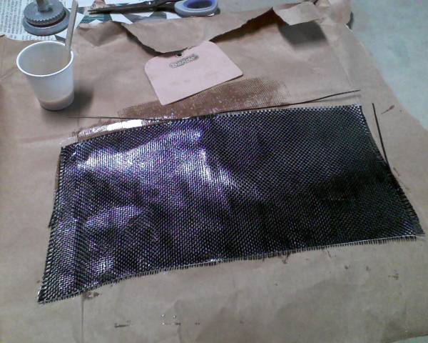
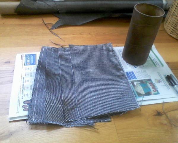
The fins will be laminated with three layers of carbon. Two layers of 5.7 oz plain weave, and one 9 oz. unidirectional layer. Here is the unidirectional carbon. The white lines are the backing glue that holds the unidirectional strands together. The backing material runs perpendicular to the carbon strands.
The uni layer will go on first. One layer of the plain weave is cut on a 45 degree bias, and will go on second. The third layer is plain weave and will go on in the 90/ 0 degree orientation. A six ounce layer of fiberglas will be placed on top.
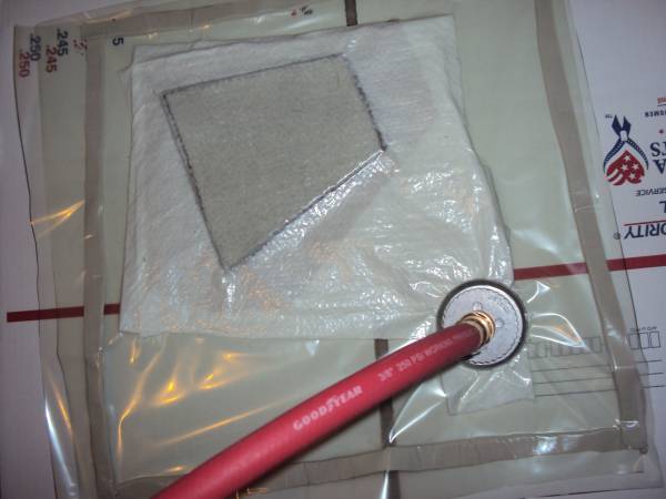
Here is one fin with a vacuum applied after laminating with the carbon pieces. I am using Aeropoxy with 60 minute hardener (3660).

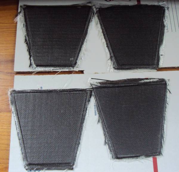
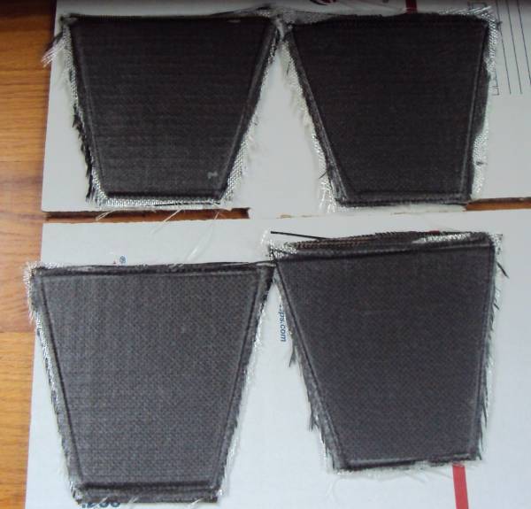
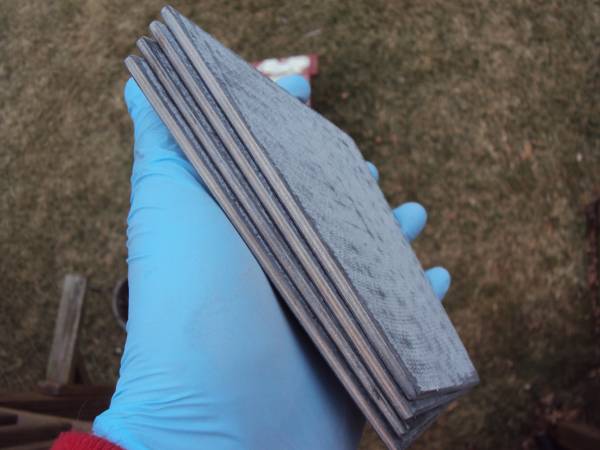
Fins Removed from Bag
2014-03-02
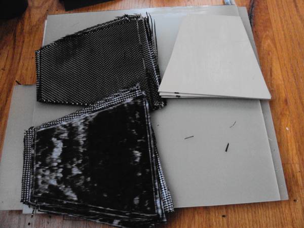
Here are the fins after vacuum bagging all four of them. Notice the lines from the backing on the unidirectional carbon pieces showing through.
The layer of 6 oz. fiberglass on top of the carbon will be mostly sanded away when I sand the fins smooth.
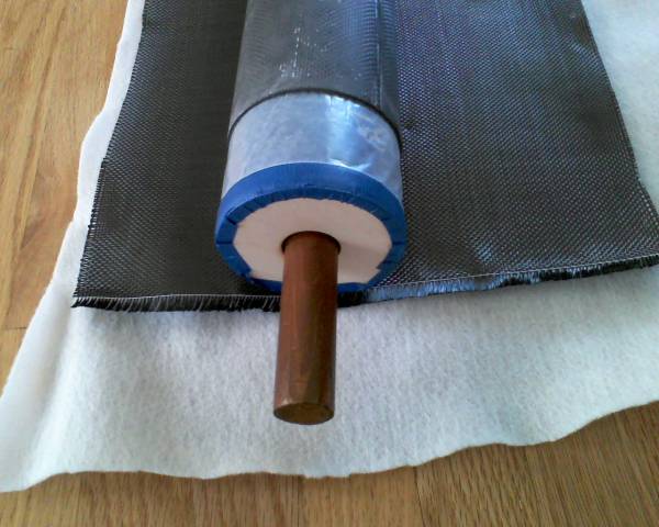
Body Tube Lamination with Carbon Fiber
2014-03-07
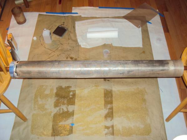
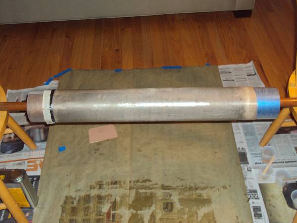
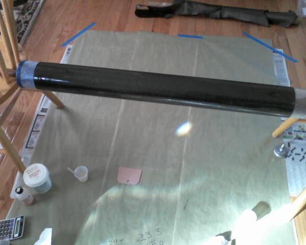
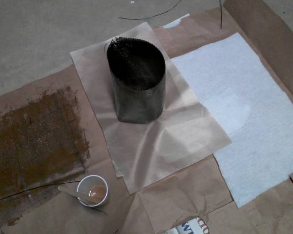
Here is the 34 inch long LOC precision tube after the outer layers of paper have been removed to reduce the diameter. The tube has been wetted out with Aerpoxy resin, prior to laying down the carbon fiber.

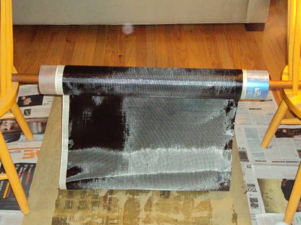
I wet out the first foot or so of the carbon cloth before starting it on the tube. The rest of the cloth gets wet out with the spreader as I turn the tube. I measured the carbon so it was long enough for 3 wraps around the tube plus an extra 3 inches. The extra gets cut off.
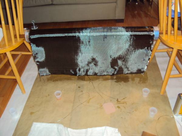
I cut the carbon, on one of the lines drawn on the carbon, after the third wrap passed the starting line that I had marked on the coupler protuding from the tube. There was probably about an extra 1/2 inch of overlap, after cutting off the excess..
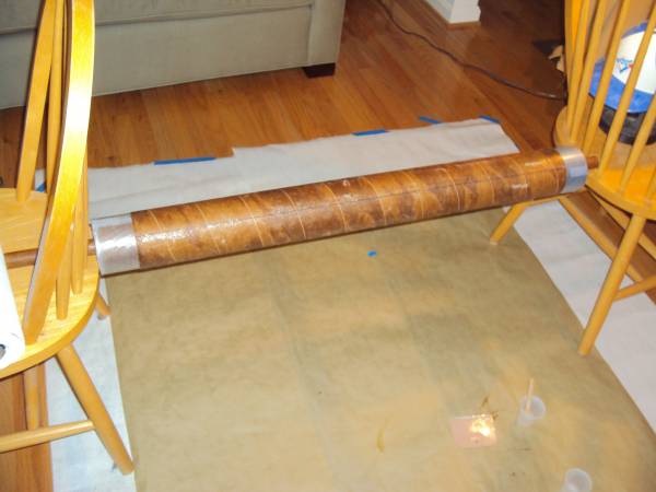
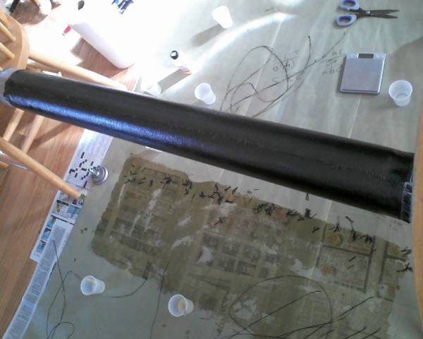
Finally, A layer of peel ply (actually it's porous teflon coated release film from Aircraft Spruce) is wrapped around the carbon. The peel ply is wetted out with epoxy using the Bondo spreader as it is wrapped around the tube, the same as with the carbon layer. Not shown is a layer of 2 oz satin weave fiberglass that I added before putting on the release film. The purpose of the satin weave is to make sure the carbon weave is thoroughly filled, by applying this extra thin FG layer on top. The fiberglass layer will be sanded off.
Cured Body Tube
2014-03-17
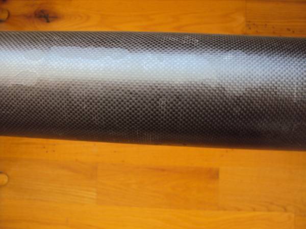
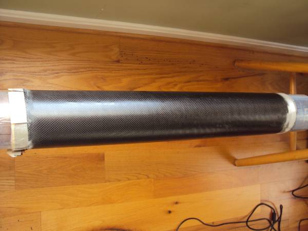
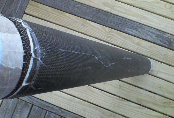
The main body tube after removing the release film:
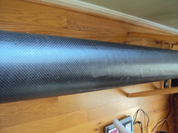
There are some voids from air pockets under the teflon release, but really they're not not too bad. I should be able to sand them out.

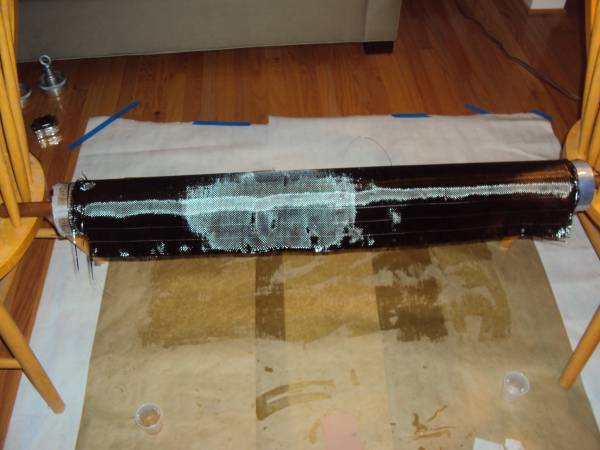
Payload Tube
2014-03-20
The CF layup on the payload tube went pretty much the same as the main body tube. The payload tube is 22 inches long.
I decided the main tube was not quite as stiff as I'd like with three layers, so for the payload tube I went with a 4 layer lay-up.
I will add a 4th layer to the other tube later. Below are pictures of the payload tube. I trimmed the edges of the cloth
more closely and carefully this time and also taped the edges with masking tape to control the edges and to keep the shape from distorting.
The results were a little better than the main tube, but doing two tubes in a row tends to produce better results the second time.

Sanding Fins
2014-03-21
I sanded the fins back to shape using 60 grit paper and a sanding block.

Adding Extra Layer of Carbon
2014-03-22
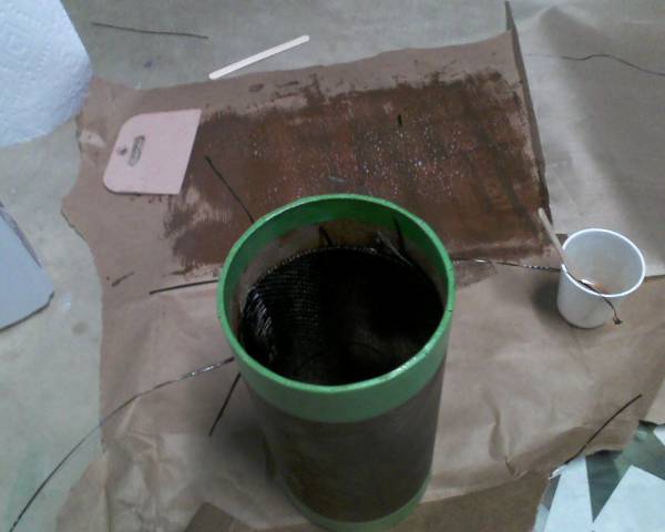
I sanded the main body tube in preparation for adding a 4th layer of carbon fiber. This just involved sanding off the veil layer of fibergalss by hand with 60 grit paper till I hit the carbon fiber. The white patches are fiberglass that was left on the tube.

I used Cotronics 4461 for this layer, because I had some leftover from another build that needed to be used.
Tube coated liberally with epoxy before applying the carbon fiber.
Added CF layer. I cut off the extra so there was hardly any overlap.
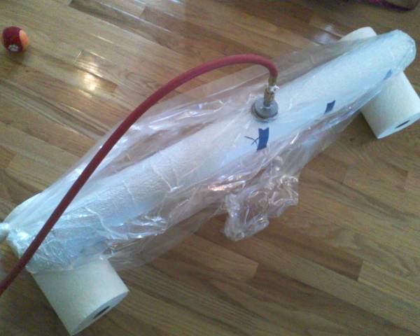
I added another layer of 2 oz fiberglass on top the carbon. Then I added the peel ply followed by breather material, before placing in the bag. I used a 55 gallon lawn and leaf bag from Home Depot.
Here I should have put the vacuum valve at the end of the tube on the coupler instead of in the middle of the tube. I just decided to leave it there.
I capped the ends of the tube with solid plywood bulkheads to keep the vacuum from sucking the bag into the tube.
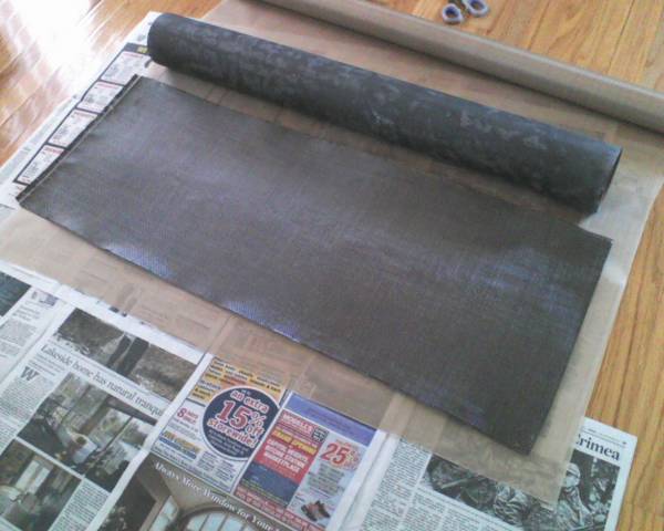
Out of the Bag
2014-03-23
Results of the vacuum bag CF layup. The fiberglass layer had some wrinkles, but the carbon fiber underneath looks good. The fiberglass layer will be sanded off again, then the fins will go on.
Fins on Rocket
2014-03-25
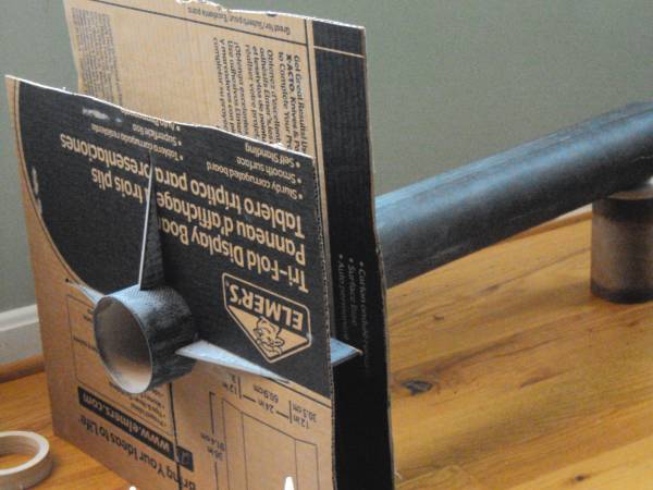
I made a fin alignment guide by recycling some cardboard pieces from my daughter's science project (conductivity of Play Doh) that was headed for the trash.
I printed out an alignment template using VCP (http://v-serv.com/vcp/), taped it to the cardboard and then cut out the fin pattern.
I tacked the fins on with 5 minute epoxy. Before putting the fins on I sanded the bottom 12 inches or so of the body tube with 100 grit paper. I still need to sand the rest of the tube.

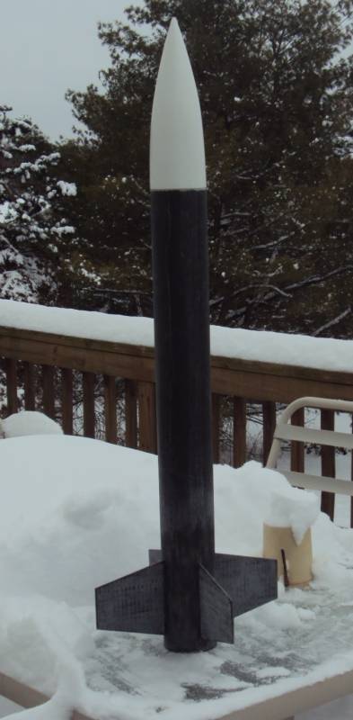
Nothing like a late March snowstorm.
Fillets
2014-03-26
I made the fillets using Proline 4500 epoxy, and a short piece of 29 mm tubing for shaping the fillets.

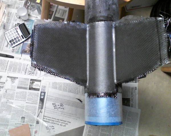
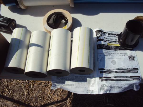
Laminating the Fin Section
2014-03-29
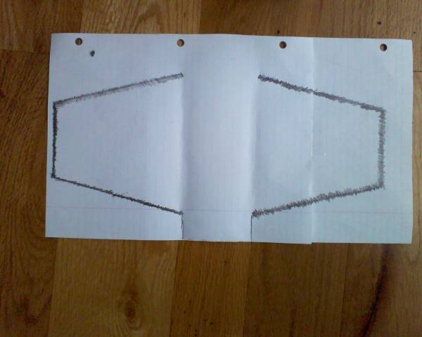
For the fin section, I planned to laminate with two layers of the same 5.7 ounce plain weave carbon fiber, tip-to-tip.
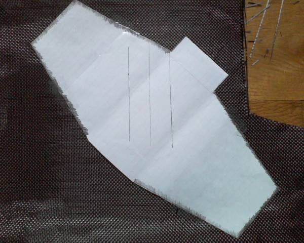
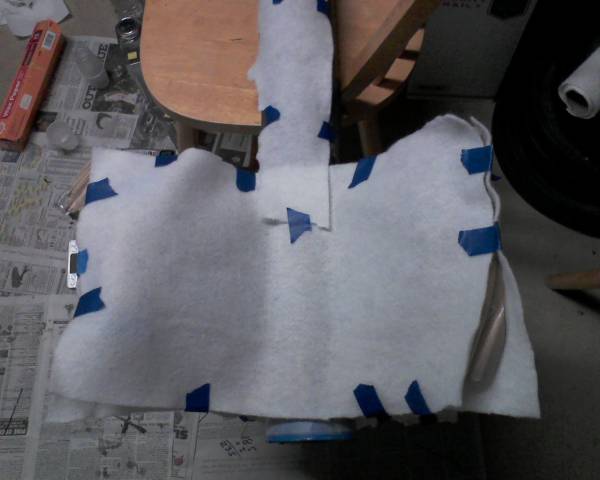
First I traced the fin pattern from the rocket with a pencil and notebook paper.

Two layers will go on. The first layer will be cut on a 45 degree bias. The top layer will be a normal 0/90 dgree orientation.
Here I am ready to cut a layer with a 45 degree bias.
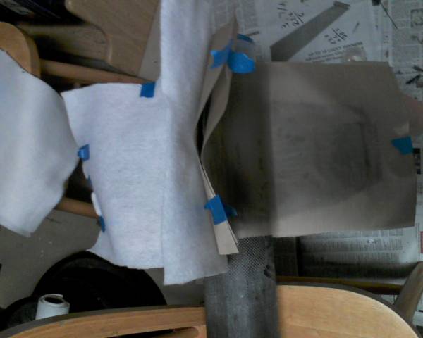
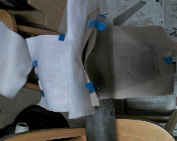
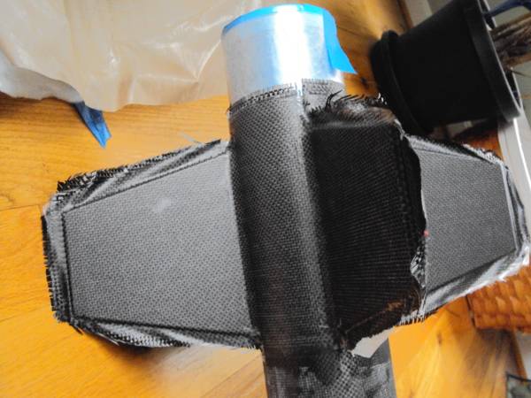
The fin section was first coated with Aeropoxy. Before hand, I had already sanded the fillets, and wiped the lamination area down with denatured alcohol.
This photo is actually the second of 4 sections being laminated. Before placing the CF on the fins, I wet out the CF by spreading the epoxy with the CF
placed on wax paper. Parchment paper works too.
This is the second layer laid down over the 45 deg layer.
Two ounce veil layer of fiberglass has been placed on top.
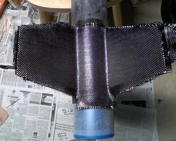
Vacuum Bagging Fin Section
2014-03-29
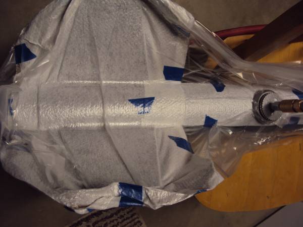
Here are a few pictures of the vacuum bagging. One layer of Teflon coated peel ply. One layer of absorbing material.
Then put inside a Home Depot trash bag.
It's in the bag. This bag is probably too small for the job. With the 34 inch length of tube it is difficult to tie a knot in the bag
and keep the bag loose enough on the fin section too. But this method is easier than gum tape and standard bagging material.
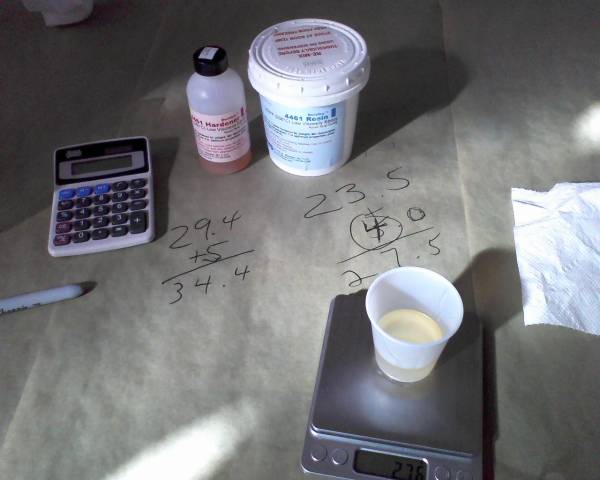
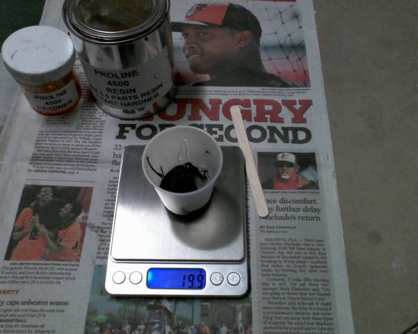
This actually took about 2 and 1/2 hours. Though the working time on the Aeropoxy is only 60 minutes with 3660 hardener, I mixed a new 25 gram batch prior to laminating for each section.
Even at two hours Aeropoxy is still pretty workable. My basement temperature was in the low 60s when I did this, so that probably extended the working time too.
(Aeropoxy specs. on working and cure times are made at 77 degrees F)
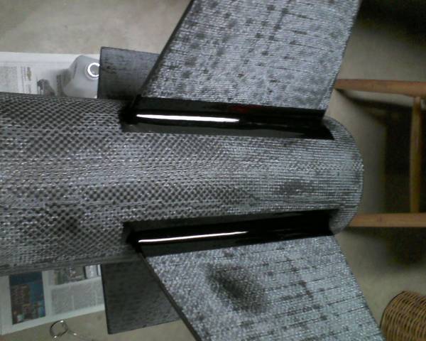
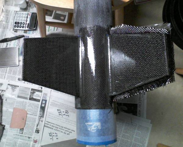
Out of the Bag
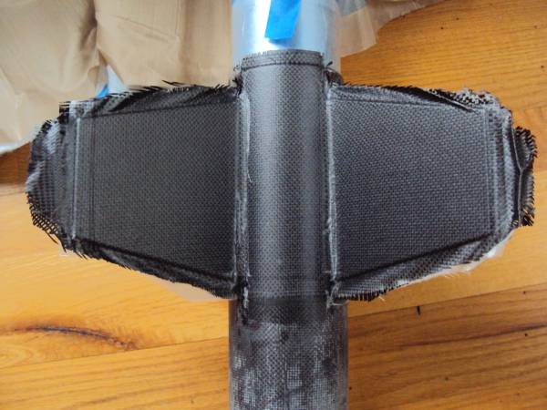
2014-03-30
A few pics of the results. The only problem was some minor bunching of the FG layer along the fillets in a couple spots. It should sand out easily.
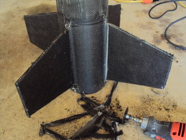
I cut off the excess with a Dremel (actually a Black and Decker rotary tool). The rest I will sand by hand.

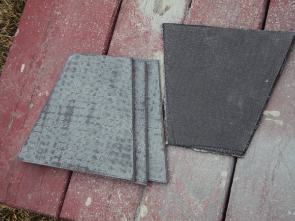
Thrust Plate
2014-04-02
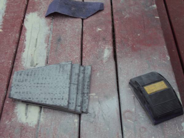
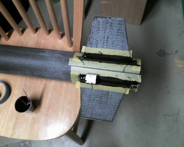
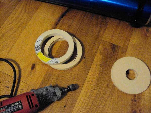
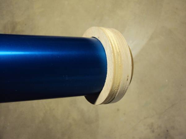
In order to fly a 75 mm motor, I needed to create a thrust plate with an OD that is the same diameter
as the airframe, and an ID the same diameter as a 75 mm motor case. I used two hole saws, a 4 1/8 "
and 2 3/4 " to cut two 1/2 inch thick rings for the thrust plate. The 4 1/8" saw made a perfect 4.0 "
OD that matched the airframe. The 2 3/4" ring was undersized, so I used a Dremel to open up the ID after
cutting the ring. A 2 7/8" saw would probably have been perfect but Home Depot did not carry one.
I tried a 3 inch saw and the hole on the ID was a little too big.
The max length case I can fit in this rocket is a 26 inch long 75/5120. A single 1/2 inch thick ring would have sufficed.
The reason for two 1/2 inch thick rings is to push the motor farther aft in order to have more recovery space.
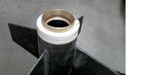
Additionally, a removable 75 motor tube with centering rings is used as an adapter.
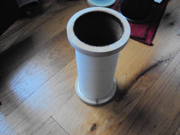
The motor is retained by securing to a forward bulkhead.

Electronics Bay
2014-04-05
I'll be using a Madcow electronics bay for this rocket. Actually I'll be re-using the bulkheads from another four inch rocket which
are interchangeable. The coupler will be new and permanently epoxied in the payload tube, with both ends being removable.
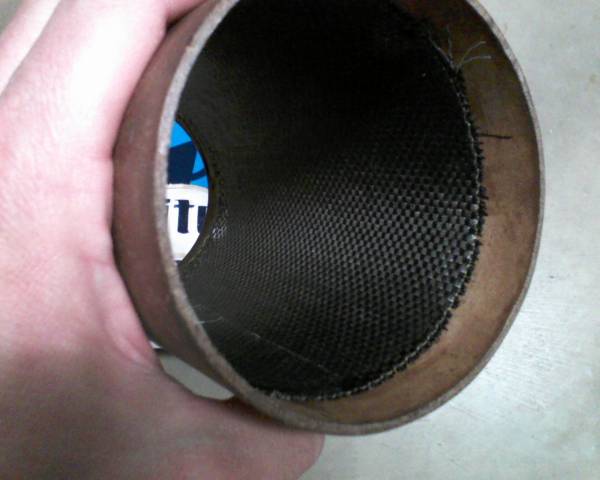
While the e-bay coupler is thicker than a regular coupler, I felt it needed some reinforcing so I laminated the inside with 3 layers of carbon fiber.
I had planned to use 4 layers, but I was using 30 minute Z poxy laminating resin and it began to thicken before I got to the fourth layer,
so I abandoned the fourth layer.

Spread epoxy.
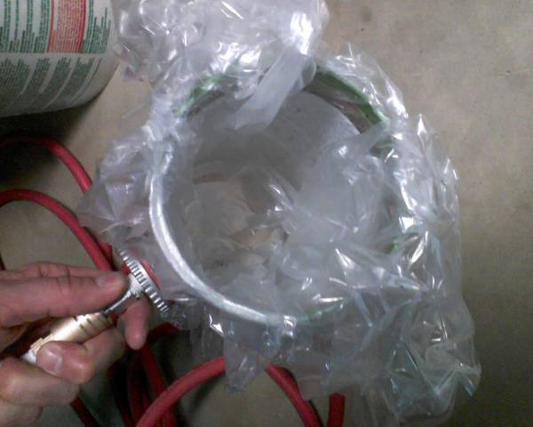
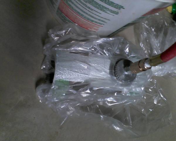
Roll CF layers into a cylinder. The diameter needs to be a good bit smaller than the ID of the coupler to get it in the tube easily without grabbing.
Place into coupler and expand outward. I used a 4 inch nose cone tip to expand the roll outward once in the coupler.
I used another 50 gallon trash bag for the bagging. A short summary of the method I used is as follows:
One layer of peel ply is placed on top the carbon, followed by one layer of breather, then place in bag.
I placed the coupler inside the bag and then pulled the bag back through the inside of the coupler, before applying the vacuum.
I think John Coker pioneered this method of vacuum bagging the inside of a tube - it is shown on his website (link to come).
Results:
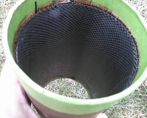
Tape Removed:
I also laminated the exterior of the coupler tube with one layer of fiberglass to increase the diameter because the coupler was a loose fit in the body tube.
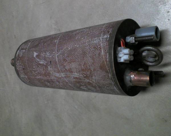
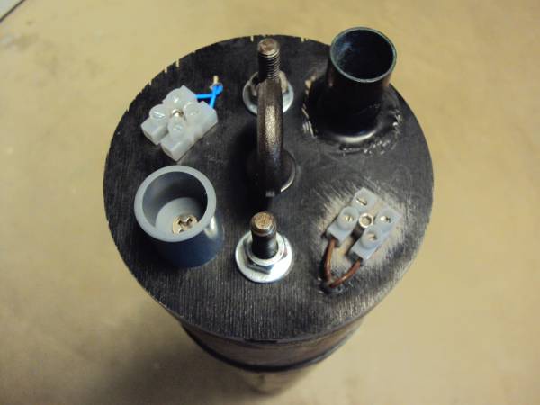
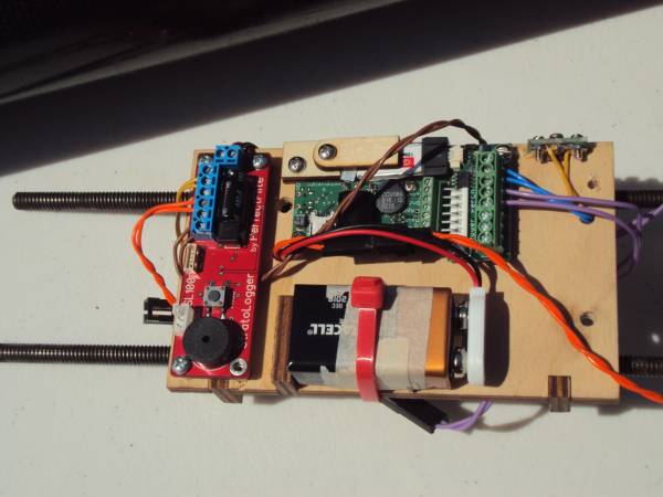
Inside the e-bay. One Raven 2 altimeter with power perch and a Perfectflight Stratologger.
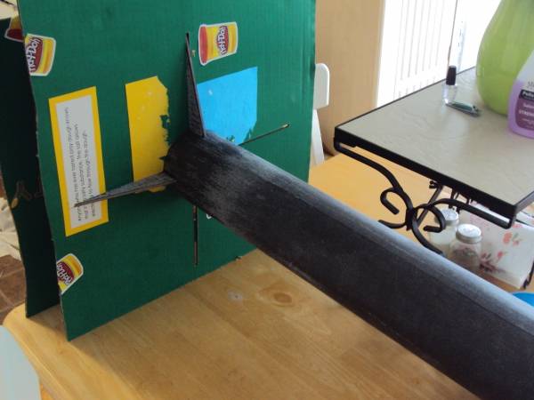
shear pin testing
2014-04-14
I tested my shear pins for strength as shown in the picture below. With the nose cone pinned with a single pin,
I pushed down on the payload tube till the nose cone separated, and watched the scale for the force required to break the pin.
The pins I tested were Evergreen styrene rod with 0.0625 and 0.080 inch diameter. I repeated the test 5 times for each size rod
and got consistent results. The 0.0625 inch rod sheared in the 20-25lb range and the 0.080 inch rod sheared at about 30-35 lbs.
For the payload tube/main deployment I plan to use 3 x 0.080 rods to give about 90 lbs. minimum protection against separation at apogee,
which works out to be about 90 gees, since the nosecone and internals weigh about 1 lb. For the drogue side/ lower airframe joint,
I chose to use 3 of the 0.0625 inch rods as pins, providing a minimum of 60 lbs. resistance to separation force after burnout. Actually my
calculations, based on mass and drag coefficients of each half show that the lower half is not subject to drag separation, so this is
just for added insurance, or peace of mind.
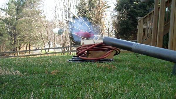
For ejection charge testing on the main, 1.5 grams was a little weak, 1.75 was good, and 2 grams was maybe a little too much.
For the drogue testing 1.5 grams provided pretty decent separation. For an actual flight, for the main, I plan to use 1.75 on the
primary charge and 2 grams on the backup charge. On the drogue side, I plan to use 1.5 grams and 2 grams as backup.
Here is a shot of the 2 gram test of the main deployment.

Finish
2014-04-15
For the finish,I applied a thin coat of epoxy. After the first coat, I sanded with 180 grit, then re-applied a second coat.
I tried to remove as much epoxy as possible while it was wet, going around the circumference with the spreader scraping it off.
I could probably do this a couple more times with finer sand paper, to get a more polished look, but it looks halfway decent as is.
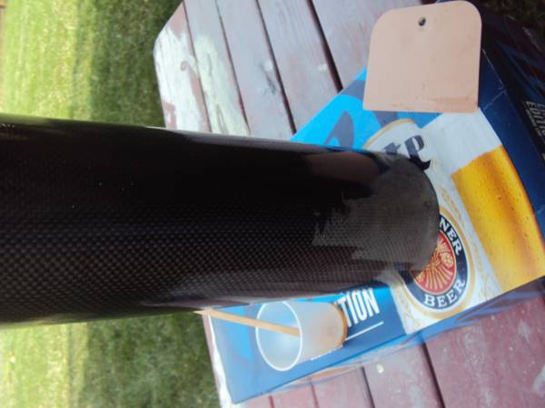
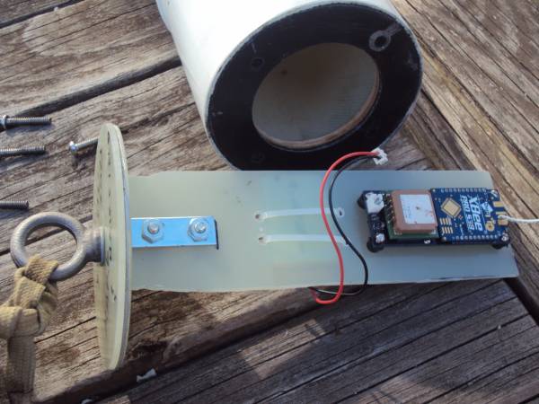
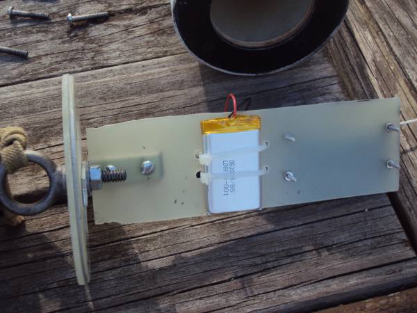
Tracking Electronics
2014-04-15
A couple pics of the 900 MHz tracker. Tracker design by Derek on TRF.
Almost Launch
2014-04-15
So I took the rocket to Red Glare 16 for the L3 cert flight. I got there a little late on Saturday,
and couldn't get it to the pad in time due to a number of things (e.g. picking up the motor,
finding my L3CC, going over the rocket with him, getting the grains stuck in the liner and a couple others).
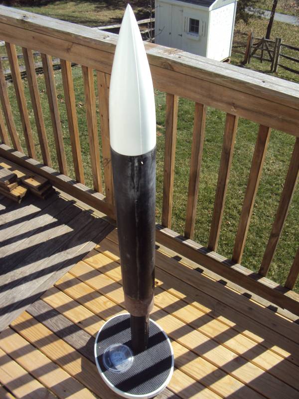
So I decided to attempt it on Sunday. Here are a few pics before taking it to the pad.
Aerotech M1500 G:

On Sunday, I had it ready to go to the pad around 10:00 am. While Saturday was perfect with winds around 5 mph,
Sunday the winds were probably in the 10 - 15 mph range with gusts even higher, and increasing as the day progressed,
but I loaded the rocket on the pad anyway.
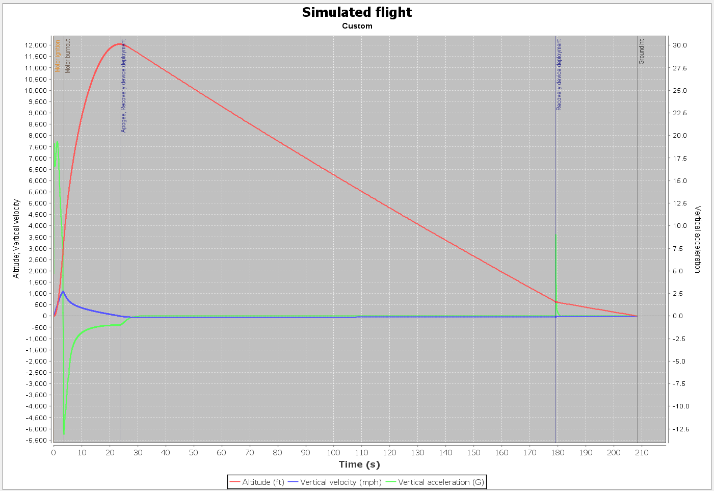
As my rocket sat on the pad, we watched another flight that went to about 8,000 ft land out by the road. Given the unfavorable
winds and wind direction, and the fact that my rocket was going to reach about 12,000 ft, my L3CC commented that I
had a good chance of landing in the trees. I concluded the same, and decided to scratch the flight and wait for another day.

Mission accomplished
2014-07-05
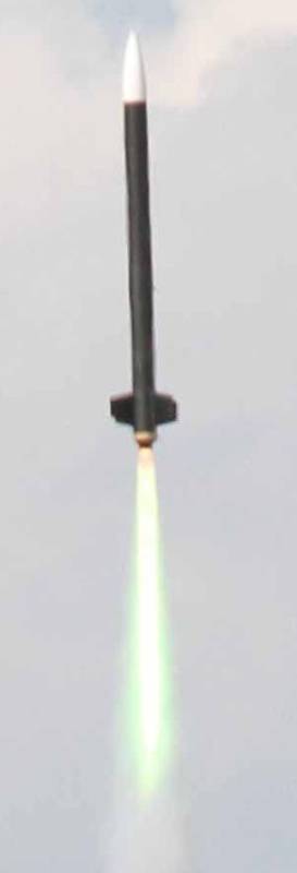
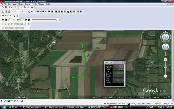
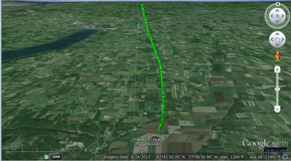
L3 flight was successful at URRF II.
i

 |
 |