Orange Whip
By Ron Beard
2012-10-02
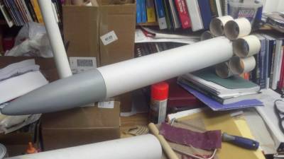
As promised, here is the build, with photos of my level 1 cert. rocket. All props to Larry Brand who inspired me with tales of his own tube-fin experimenting on this very site!
Lots of home-made parts and low cash expenditure are the hallmarks of this great flyer.
Flys on G through J impulse motors so is good for Mid-power, Level 1 and Level 2 flights! (yes . . . really!)
Basic Construction
2012-10-02
The body tube is a standard Staples or Office Depot purchased, 4 inch diameter mailing tube - about $12 ordered online. no special prep other than sealing well with sanding sealer and several coats of paint.
The tube fins are cut down 3 inch mailing tubes of the same pedigree as above - 1 tube, about $5. epoxied lightly inside and out then sanded smooth to prevent high-speed delamination
The motor mount tube was purchased online and is a standard 38mm LOC MMtube. $4.00 online. 20 inches and open at the end. Tube fin rockets have a weird CP/CG relationship which allows you to pretty much stuff the motor tube with as long a motor as you can find. Even a little extra poking out of the end is not a bad thing. See Larry Brands excellent research on this subject on this site.
The centering rings were hand made by laminating 2 layers of 3/16 balsa with 3 layers of heavy construction paper - maybe $2. see a more detailed expalination at the end of this article.
The nose cone was hand made using rings from 2inch thick DOW styrofoam wall insulating sheets and 3/16 balsa sheet rings then covered with a pantyhose and some 30 minute epoxy. - $8 bucks or so. Totally hand made without power tools/lathes etc. Massive pain in the butt . . satisfying in the end but comes with a great case of "tennis-elbow" from all the sanding!
The recovery system is braided Kevlar/standard braided nylon bungee cord/nomex chute protector/nylor chute. I had all of this stuff on hand, but purchased - maybe $35.00
Finishing and sundry bitz - $10
All up weight is around 36 ounces (plus whatever motor you use) and length is right at 3 feet. Flights tend to be slower because of the drag effect of the tube fins and care should be taken to simulate any flight you even think might approach 400 miles per hour or faster as the design will most likely disintegrate at or above these speeds (it is just really cardboard and paper after all!)
So, for around $75 and a decent ammount of work, you get a very versitile, interesting, durable flyer that should not only let you certify simply and safely, but will continue to be a fun rocket in your fleet and certaily one you can experiment on without the "ouch factor" if you make a mistake (hasn't happened to this one yet but I have some plans . . . MUAHAAHAAAHAAAA!!!)
-untitled-
2012-10-02


Of Note: Engine mount
2012-10-02
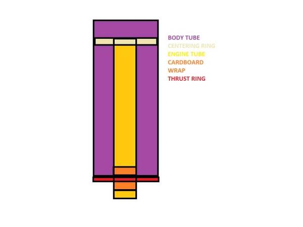
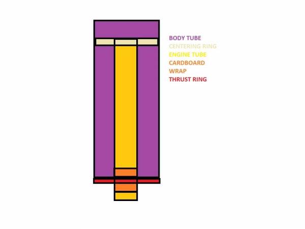
As mentioned above the engine mount tube is standard LOC material but the intallation is not. First, the centering rings were made by laminating 3/16 balsa sheet in between layers of heavy construction paper using Titebond II like this:
Heavy CP
Balsa
Heavy CP
Balsa
Heavy CP
A sheet of this "poor-mans composite" material was created that would be big enough to cut out 2 - 4inch rings from. Lay up the sheets like you're laminating fins then press on a flat surface under a big ole stack of books for a day or so. When finished, trace out the pattern and cut out the holes for the motor tube first then cut the rings themselves out. Rough fit them to the end of the body tube making to sure to sand them a little bit "loose". I wanted the front CR to slide freely up into the body tube as normal but then i decided the aft ring should act as a thrust ring as well ands so sanded it just to the OD of the body tube itself. at this point, the rings should be tacked to the engine tube with CA and don't forget a little relief hole in the top ring so you can thread a kevlar shock cord through! Since the bottom ring was also going to act as a thrust ring and have a great deal of pressure placed on it by the thrust of the motor, i wrapped the engine tube 6 or 7 times, above and below the aft ring with a 1 inch strip of construction paper and titebond. The idea is that the engine tube is so well adheared to the aft centering/thrust ring that no failure due to overthrust will occur. The inside of the outside of the whole motor mount assembly was then epoxy coated and inserted into the bottom of the body tube. I used a big batch of 5 minute epoxy for this and then did a move i call "the twisty toss" which is where you toss the body tube slightly into the air while holding it vertically and impart a rapid twist on the tube as you do it. This forces the epoxy to flow onto the inside walls of the body tube and after 3 minutes or so of this, things have pretty well solidified. Last but not least, the equivalent of a 2 inch tube coupler (created by taking a slice out of an extra piece of 4 inch mailing tube so it fits down inside the body) is pushed all the way down so it buts against the top of the motor mount assembly then epoxied in place. This method creates a medium weight but uber bullet proof mount that, short of the material itself failing, will not be defeated by even the highest thrust 38mm motor I could stuff into it! See the diagram below.
Post production:
2012-10-02
This rocket is completed and has flown well on a G-79 and an H-128. The boost is always strait and the rocket does not weathercock much either. I will post a full review soon with more pictures from the upcoming "Buckeye Blast" November 10th 2012 (see torc703.org for details) where she will fly again maybe on an I or maybe even a J motor if I can find a donor case!!
 |
 |