| Manufacturer: | Paper |
BRIEF:
Conversion of a Currell Graphics 1/144 scale Soviet N-1 paper model to fly on 24 mm motors. The plans are available at the Currell Graphics website.
The N-1 rocket was the Soviet answer to the American Saturn V moon rocket of the 1960's. The Soviet plans to beat the United States to the moon depended on the enormous N-1 booster. The N-1 was more complex than the Saturn V in that it consisted of five stages and a total of 30 engines in the first stage alone. The complexity of the rocket translated into poor reliability. The N-1 rocket failed all four times it flew. The second launch in July 1969 was a spectacular failure as the first stage engines shut down shortly after launch and the resulting explosion from the falling rocket completely destroyed the launch site. After the final flight failure in 1972, the remaining unflown rockets were scrapped and the Soviets abandoned their human lunar ambitions.
TOOLS:
- White glue
- Yellow glue
- CA glue
- Glue applicator such as wooden toothpicks
- Scissors
- Sharp knife
- Circle cutter
- Flat cutting surface
- Ruler/straight edge
- Clear Coat
PARTS
- 65 lb cardstock
- 110 lb cardstock
- Poster board
- BT-60 tubing
- 24 mm motor tube
- 24" parachute
- Shock cord material
- Ballast (washer, nut, and bolt)
- Screw eye
MODIFICATIONS:
This review will only document the changes required to build a flying model.
The N-1 paper model consists of two sets of parts and instructions. The first set is for the first stage (with a Soviet designation of Block-A) containing nine parts pages and five pages of instructions. The second set builds the upper stages and contains six part pages and six instruction pages. All aspects of the card model are outstanding. The instructions are excellent in detail and clearly show how the parts are assembled. The parts print crisply and the fit is perfect.
Construction of the model begins with the first stage. All first stage parts were printed on 65 lb cardstock. The first stage skin segments were built as specified in the plans. A hole was cut in the center of the base plate to allow a 24 mm mount to be placed between the eight inner engines of the N-1 first stage.
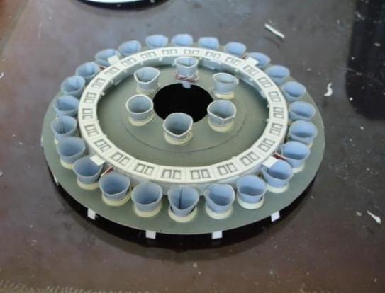
Figure 1. Completed First stage baseplate with hole cut for the 24 mm motor tube.
The 24 mm motor tube was glued into a BT-60 chute tube using home made centering rings. The former rings used to stiffen the outer skin of the rocket were reinforced with poster board. The holes cut in the former rings were sized to hold the BT-60 tubing. A hole for an internal launch lug was also cut in the formers.
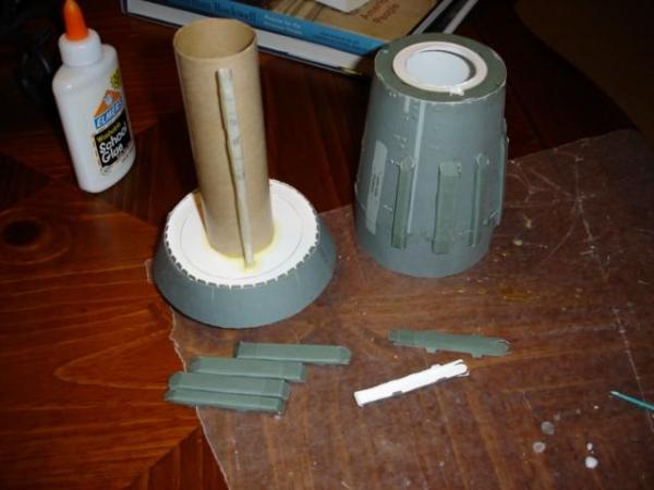
Figure 2. First stage chute tube with internal launch lug.
The upper tank segments of the first stage were modified to accommodate the ejection of the parachute. I chose to separate the model at the first/second stage split. The first stage contains all the recovery equipment. A coupler was glued to the upper fuel tank segments. A screw eye was glued to the coupler to attach a shock cord and parachute.
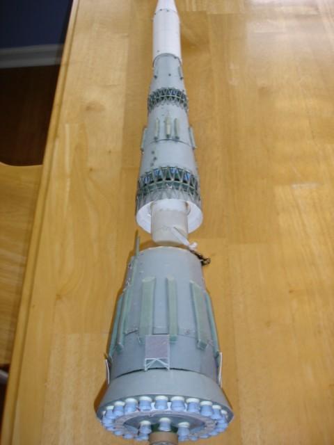
Figure 3. First stage fuel tank segment attached to second stage by trusswork. Note coupler.
The first and second stages of the N-1 rocket were connected by an interstage trusswork. I glued the trusswork directly to the upper tank segments as opposed to the specified points marked on the first stage body. This was required because of the recovery design. A similar trusswork connects the third stage to the second stage.
The interstage trusses were built as per the instructions, but were reinforced with CA glue. An internal former ring was added to the trusses for additional stiffness. At the start of the project I anticipated the strengthening of the trusses to be the most critical modification for the model to be a successful flyer. The combination of the former rings and CA resulted in strong pieces that handled flight conditions.
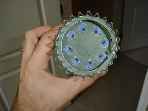
Figure 4. First stage truss detail looking forward to the aft end of the second stage. Note former ring with notch and hole cut for internal launch lug.
The first stage stabilizer grids were glued to the model in the stowed position. The plans call for them to be applied in the deployed position, but it was decided they might not withstand the rigors of launch/landing in that configuration. The stowed position was simpler to implement and required fewer modifications.
The upper stages were constructed essentially to plan. The internal former rings were reinforced similarly to the first stage. The second/third stage interstage truss was reinforced with CA and a former ring similarly to the first/second stage truss.
A hole was cut in the base of the second stage to allow for the internal launch lug to pass through. Great care should be taken to ensure the proper alignment between the first stage and the upper stage launch lugs. The launch rod exited the rocket approximately in the middle of the second stage between two of the fuel line fairings. I added an extra fairing to mask both the lug and the hole required for the rod to exit. With more thorough planning, the rod could be planned to exit the model closer to the second/third stage connection. This would probably look better aesthetically than my model.
The upper payload shroud was reinforced with an additional layer of cardstock to increase strength. Nose weight was added using a bolt, nut, and several washers. Approximately 1.5 ounces of nose weight was added to the model.
The N-1 required the application of many exterior detail pieces. All of these were added to my flying model. The detail pieces are time consuming to apply, but the resulting model looks more polished and complete.
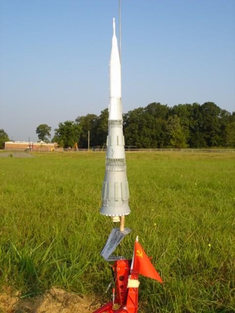
Figure 5. Completed N-1 on the pad and ready for launch.
Stability was checked using a swing test. An Estes C11-3 was placed in the model and prepared for flight conditions. The initial swing test was not encouraging. The model flew tail first. More nose weight was added to push the CG forward to the base of the second stage fuel line fairings. The model still flew tail first.
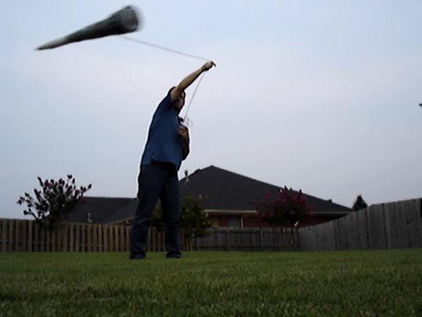
Figure 6. Swing test.
After consulting the folks on The Rocketry Forum it was suggested I use the VCP program to check the stability. VCP uses the Barrowman equations to determine the center of pressure. Being a series of transition segments, the N-1 is an ideal candidate for these equations. VCP showed that the model had approximately 5-6 cm of static margin.
The VCP file has been enclosed.
RECOVERY:
For recovery, a single red 24" mylar chute was attached to a shock cord. A tri-fold mount was selected to secure the shock cord to the model. An Estes Saturn V like dual recovery was considered and rejected, but could be implemented.
FLIGHT:
Encouraged by the VCP results flight day finally arrived. Loaded with parachute, wadding, and motor the model weighed approximately 7 ounces. An Estes C11-3 was chosen for the first flight.
After a short countdown the N-1 took flight. Boost was arrow straight to ~125 feet. No stability issues were noted. The parachute deployed properly, but the shock cord was burned through by the ejection charge. The first stage tumbled in ballistic but landed safely in tall grass with no damage. The shock cord mount may have been glued too close to the motor and the wadding did not adequately block the hot ejection particles.
The upper stage came down safely on the 24" mylar chute. There was some damage to the escape tower so the Estes trapeze recovery method will be re-examined for future N-1 flights.
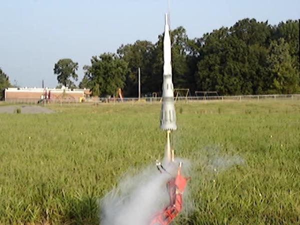
Figure 7. Liftoff of the N-1!
SUMMARY:
This first flight was considered a success. It flew straight and did not get destroyed. The minor escape tower damage has been repaired. Once the shock cord has been replaced further flights of the N-1 will occur on Estes D12-3 motors.
This was a challenging project that took three months from first cutting to launch. It pushed my skills in many directions. Seeing the N-1 soar of the pad and into the air was definitely a gratifying feeling.
I want to thank the many people on The Rocketry Forum who encouraged me or assisted me when I had questions. Many of their ideas ended up in the final product.
 |
 |
|
|
Robert A. Morstadt (January 11, 2023)
Excellent project !