Currell Graphics SpaceShipOne (Version X1) Plan
Currell Graphics - SpaceShipOne (Version X1) {Kit}
Contributed by Dick Stafford
| Manufacturer: | Currell Graphics |
(Contributed- by Dick Stafford - 10/06/04)
Brief:
October 4th, 2004, heralded a new era in space exploration. On that day, Brian Binnie piloted Scaled Composite's SpaceShipOne to 367,442 feet (112 kilometers), capturing the $10M Ansari X Prize. Later that day, I learned of Currell Graphics' SS1 paper model and immediately wanted to convert one for flight.
Currell offers two versions: the original version and the X1 version that made the two historic X Prize flights. I chose the latter. Prior to building the model, I opted to convert it for MicroMaxx motors. As you will read, this model is a bit too big to be a great flier on these small motors but shows promise for a 13mm conversion.
Modifications:
The instructions for the SS1 are five pages long and include a bit of history, some narrative, and an excellent set of illustrated directions. This is one of the most complex paper models that I have ever built. It includes over 85 parts, many of which are quite tiny. Being that I am not a stickler for detail, not to mention "all thumbs", there were around 30 parts that I didn't use. Many of these were for the "gear down" option.
The most important tool required is a new hobby blade. I also used a cutting mat, scissors, a couple of toothpicks, and some small clamps. I built it mostly with white glue but used Perfect Glue to tack down the Kevlar® twine and attach the plastic lug.
I will emphasize how I modified this model for flight. The instructions are freely available and are very good. I will reference the steps as I go and will identify specific parts as required.
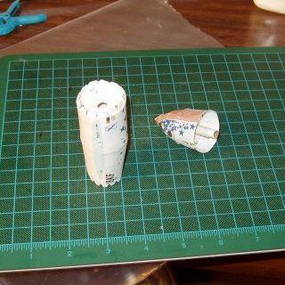 Nosecone (a.k.a. front fuselage) - This section spans two steps and requires around 14 parts. It is comprised of several cones/transitions with center bulkheads, which come in pairs. Since I thought I would eventually need nose weight, I filled the small tip with clay. I cut holes in the bulkheads A9--A12 to accommodate the 6mm tube. I also replaced the smallest bulkheads, A7 and A8, with a 6mm--10.5mm fiber centering ring. I could have cut these bulkheads, but they are tiny. A 1.75" piece of 6mm tube extends from the clay to just past the last transition. You need to make sure it doesn't stick out too far lest it interfere with the bulkhead in the next section. I inserted a piece of T2 tubing (which telescopes into the T2+) to form a shoulder. This was not glued in. The nosecone assembly can be seen in the first photo.
Body (mid- and tail sections) - This section consists of more paper transitions and bulkheads. It spans steps 3, 5, 9, and 19 and consists of around 15 parts. Steps 4, 6, 7, and 8 are all related to the landing gear option and I didn't need these for a flying model. As you can see, I also jumped ahead in the instructions to complete the body in one stretch. The first photo also shows the partially completed body section.
Again, I cut holes in all the bulkheads. The motor tube extends from the nozzle to just above the top bulkhead. I cut this tube to fit by installing the nose and pushing the lower tube up until it seated on the nose assembly's shoulder (the T2 tube). I then marked its location and glued it in. When installed, the nose assembly seats against the glue tabs that extend out of the mid-body. I had anticipated removing these tabs and adding solid neck, but this wasn't required.
Main wings - These wings each consist of eight components and their construction//installation spans four steps. All the wings on this model are constructed using ribs/spars and outer shells so they are reasonably complex. The subtle angles and bends on these components are truly impressive. Be wary of too using too much glue, as it will warp the small pieces quite badly (not a theoretical observation). I had trouble getting all the small components together nicely, and even ended up leaving the thin trailing edge strip off. I'm sure many of you can and will do better.
The wings slide onto two spars that you previously install through the body of the SS1. When building the wings, make sure the holes for the spars are aligned and are big enough! No theory here either.
Side booms (the vertical wings that extend toward the rear of the bird) - These have 7 parts each, cover three steps, and are both smaller and more tricky to assemble than the main wings. They are built-up from 2 spars, 2 inner surfaces, and 2 outer wraps. One of the spars is 7 ½" long, has 16 bends, and circles the edge of the wing assembly. My side booms came out pretty rough. They attach to the rear half of the main wings and a small printed component covers the front half.
Stabilizers - These are a lot simpler than their bigger cousins are. They consist of 4 pieces and are installed in 2 steps. Even I got them right.
 Finishing touches - The last 2 steps of the instructions is detailing that I left off. All I had left to do was to attach the lug (piece of a pen's ink tube) to the underside of the wing, install the Kevlar® twine, and add nose weight. Curiously, the "finishing touches" didn't require any finishing since the model is pre-printed. I didn't even shoot on a clear coat to protect the ink, although this is a good idea if you will fly in damp conditions.
Stability - Micromeister (from TRF and the MicroMaxRockets Yahoo group) graciously provided the CG for his successful MMX SS1 (plans are available on the Yahoo group). I scaled that CG (1.09375") to this larger model (64.8mm), and headed to the Rocket DungeonTM to install nose weight. After adding ~4g of shot, the total vehicle weight was 18g and I had only moved the CG about half the distance I needed to. As this was pushing the max weight for a MMX-II motor, I decided to give it a try as is.
Construction:
Items needed:
- 3 sheets of white cardstock
- ~6" of Totally Tubular T-2+ tubing
- ~1" of Totally Tubular T-2 tubing
- 1 6mm--10.5mm centering ring
- Clay and lead shot
- Piece of a BiC pen ink tube
- Kevlartwine
Flight:
I flew it three times and each profile was about the same: slow boost, arcing flight, ejection just before "landing". Apogee was estimated to be 10', 6' and 10', respectively. On the last flight, the Kevlar® broke free from the body, which was easily repairable. Note that I do not endorse my positioning of the CG. This model could very well have been unstable had the flight been higher and longer in duration.
Summary:
This is a very detailed and small model. Despite excellent instructions, I found it difficult to build. You definitely need a sharp knife, good light, a steady hand, and patience.
The flight conversion was straightforward, but the model, once properly balanced, is too heavy to be a great candidate for MMX. I offer these suggestions based on my experience:
- Add the lead shot at the very tip. I had filled it with clay. I managed to remove some, but still had most of the weight a bit further aft.
- Look at reducing weight while keeping the basic paper kit.
- Consider a 13mm conversion (this will have its own challenges). The paper kit is tough enough for MMX but more reinforcement may be needed on the booms to handle the increased thrust.
 |
 |