| Construction Rating: | starstarstarstarstar_border |
| Flight Rating: | starstarstarstar_borderstar_border |
| Overall Rating: | starstarstarstarstar_border |
| Manufacturer: | Performance Rocketry  |
Brief:
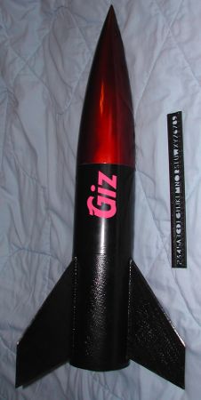
This Performance Rocketry Econoline kit is short (33 inch) and fat (5 inch diameter) and made from all fiberglass. It
is similar to a Fat Boy on steroids with a pointy nose cone. The kit is designed with the experienced builder in mind
as there are no instructions included. Additionally, the only parts included are the basic airframe parts. The builder
needs to add motor retention, rail/rod connection, and the entire recovery system (including connectors to the
airframe), and insuring along the way that the completed kit is stable. The lack of instructions and missing pieces
allow each builder to customize the rocket according to their particular construction skills and to a design that they
are happy with flying.
Construction:
For me, the purpose of this kit was to learn how to laminate carbon fiber. Building the kit this way is not required.
I also wanted to use this as the fin can and nose cone of a taller rocket by adding a four foot middle section to
enable dual deploy and fly it on larger motors. The middle section is not covered in this article, but an incredibly
strong fin can is created by building it the way I describe. Finally, there is no description of the layering required
to do epoxy/carbon fiber lamination. There are other sources of this information which I used as the basis for my work.
The parts list included with the kit is short:
- 1 nose cone
- 1 nose cone bulk plate
- 1 pre-slotted airframe
- 1 54mm motor tube
- 2 centering rings
- 3 beveled fins
I added the additional materials to complete the construction (all metal is stainless steel):
- 36in x 54in carbon fiber
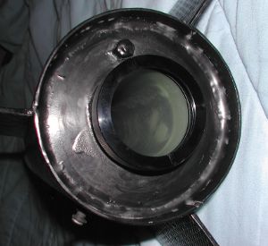
- 1 54mm Aeropack retainer assembly
- 1 U-bolt, ¼-20 for ½ inch pipe, with mounting plate
- 8 ¼-20 nuts
- 9.25 inches ¼-20 allthread
- 6 ¼-20 body washers, 1 ¼ inch
- 1 ¼-20 forged eye bolt with shoulders and 1 inch of thread
- 3.9 inch x 12 inches phenolic tubing
- 2 8-32 T-nuts
- 2 8-32 x 1 inch round head screws
- 2-8-32 washers
- 2 rail buttons for 1010 rail
- 3 3/16 inch quick links
- 15 feet Kevlar® strapping with loops at both ends and one in the middle
- 9 inch Kevlar® parachute protector
- 1 Top Flight 50 inch standard parachute
The cost of the additional materials is as much as the kit, so realize that this kit is not as inexpensive to build as it first appears. Additionally, I needed the following items to aid in the assembly: 1 nylon 8-32 bolt and 1 6in band clamp, not counting the myriad of clamps for the lamination.
Before assembly, I stacked the two centering rings on top of each other and drilled a 9/32in hole through both of them in the center of the ring. I used the same bit to drill a hole in the center of the U-bolt mounting plate. Lining up the center hole in the mounting plate with the hole in one of the centering rings, I then drilled two more holes in the centering ring in line with the U-bolt holes to create the forward centering ring. Next, a 4in hole saw was used to cut the nose cone bulk plate into two pieces: a centering ring and a bulk plate.
In dry assembly, I noticed that the motor tube was only 1/16in longer than the two centering rings, fin chord, and space required to attach the Aero Pack retainer. Assembly started by epoxying the forward centering ring to the motor tube 1/16in from the top of the motor tube. This assembly was inserted into the base of the airframe just far enough for the fins to fit with the U-bolt holes centered between the fin slots. The rear of the rocket was covered with two layers of waxed paper and the rear centering ring was temporarily slid into place. Next, waxed paper was used to line one airframe slot so that nothing would stick to the airframe. Epoxy was put on the chord of one of the fins and it was glued perpendicular to the motor tube through the slot in the airframe. Once this was hard, this process was repeated two more times for the other two fins. I then numbered each fin and put the corresponding number on the airframe next to the fin. Finally, I drew lines on both sides of all fins where the outside of the airframe was.
After everything had cured solid, the rear centering ring was removed (the pre-drilled hole made it very simple) and the airframe slots were extended aft to allow removal of the fin/motor tube assembly. The fin to motor tube joint was reinforced with an epoxy/carbon fiber layer from about one inch up the fin to one up the neighboring fin. This would ultimately be completely within the airframe. The same epoxy/carbon fiber was added to all three sections between the fins, making sure the aft centering ring would still fit on properly and none of the carbon fiber interfered with sliding the motor mount back in place.
 Next, the U-bolt was added to the forward centering ring, with just nuts above the centering ring and
nuts and the mounting plate below the centering ring, making sure the center holes were aligned. Then the allthread was
inserted so that it barely stuck out forward of the centering ring and nuts were added both on top and bottom to lock
it in place. This assembly was reinserted into the airframe. With the aft end up, epoxy thickened with microballoons to
the consistency of honey was poured into the space between the motor tube and the airframe, approximately ¼ inch
thick in each of the three sections. Immediately after doing this, the rear centering ring was again temporarily
installed and a 6in band clamp around the aft of the airframe was tightened to make sure things continued to stay
centered.
Next, the U-bolt was added to the forward centering ring, with just nuts above the centering ring and
nuts and the mounting plate below the centering ring, making sure the center holes were aligned. Then the allthread was
inserted so that it barely stuck out forward of the centering ring and nuts were added both on top and bottom to lock
it in place. This assembly was reinserted into the airframe. With the aft end up, epoxy thickened with microballoons to
the consistency of honey was poured into the space between the motor tube and the airframe, approximately ¼ inch
thick in each of the three sections. Immediately after doing this, the rear centering ring was again temporarily
installed and a 6in band clamp around the aft of the airframe was tightened to make sure things continued to stay
centered.
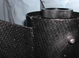
A line was drawn about 1/8in above the top of the fins to serve as the upper limit of the lamination. Epoxy/carbon fiber was added from fin tip to fin tip for one third of the rocket with the aft centering ring protected by waxed paper and a band clamp around the bottom of the rocket to keep things tight. When the epoxy was stiff and all clamping and additional lamination materials were removed, the carbon fiber was trimmed to the fin pattern. There was a small tab of material underneath the fins that was cut from the fin but left attached to the airframe. More epoxy was added underneath this and this tab was laid down on the adjacent airframe, again being clamped in place. This created a connection between the airframe pieces behind the fins. When all three sides were done, the airframe was continuous.
Note: One trick for applying pressure to the curved airframe between the fins that I used was to take a piece of Lucite and put it on the airframe prior to beginning anything. I then heated it with a paint peeler and it sagged to the curve of the outside of the airframe. It was cut to be ¼in narrower than the space between the fins to prevent a sharp angle in the carbon fiber where the fins meet the airframe.
When all the epoxy had cured, the aft centering ring was removed and two 5/32in holes were drilled in the airframe for the rail buttons. The forward was ¼in below the top centering ring and the aft was ½in above where the aft centering ring would be. The top of the T-nut was roughened up with a grinder then bent roughly to the curve of the airframe. Epoxy was put around the outside edge of the T-nut and the nylon bolt was inserted and then the head cut off. This assembly was put into the upper hole for the rail button with long nose pliers held tight with a good rubber band. The nylon bolt served to prevent the epoxy from touching anywhere except when the T-nut was properly positioned. It also allowed a temporary nut to be added to "clamp" the T-nut in place until the epoxy cured. The nylon bolt was removed and additional epoxy was put around the base of the T-nut with a long stick to insure it would not come lose. The aft T-nut was easily reached and was done more simply but following the same process.
 Small internal fillets were added between the fins and the airframe and then the aft centering ring was
installed, making sure to line up the allthread hole. A washer and nut was put on top of the allthread and lightly
tightened. Then the joint between the centering ring and the airframe was epoxied and filleted. The Aero Pack retainer
was installed per the instructions that come with it using JB Weld high temperature epoxy. This same epoxy was used to
fillet the motor mount to the aft centering ring. The forward centering ring was then also filleted from above.
Small internal fillets were added between the fins and the airframe and then the aft centering ring was
installed, making sure to line up the allthread hole. A washer and nut was put on top of the allthread and lightly
tightened. Then the joint between the centering ring and the airframe was epoxied and filleted. The Aero Pack retainer
was installed per the instructions that come with it using JB Weld high temperature epoxy. This same epoxy was used to
fillet the motor mount to the aft centering ring. The forward centering ring was then also filleted from above.
The rail buttons were added by screwing in the 8-32 screws into the T-nuts with a drop of thread locker to prevent accidental unscrewing. Each rail button was spaced from the airframe by a washer.
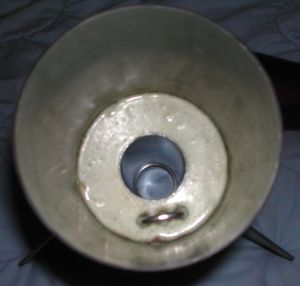
There is almost no space in the airframe for recovery devices, so a phenolic tube was inserted into the nose cone to more than double the available space. Without this extra space, the parachute and recovery strapping would not allow the nose cone to seat all the way down.
The center portion of the divided nose cone bulk plate was epoxied and filleted in the end of 3.9in phenolic tube. The eye bolt was inserted with the eye inside the tubing and the body washers were added and capped off with a nut. Thread locker was added and this was tightened. This assembly was inserted into the nose cone with the washers pointing toward the nose. The phenolic was marked about 1/8in shorter than the end of the shoulder of the nose cone. The phenolic was removed and cut to this line. The phenolic tube was reinserted into the nose cone and with the nose cone pointing down, more mayonnaise consistency epoxy was poured between the tube and the nose cone. The centering ring portion of the nose cone bulk plate was temporarily installed to make sure the tube was centered. When this epoxy had cured, the centering ring was removed and more epoxy added, making sure there was a good connection between the phenolic and the nose cone. After curing, then the centering ring was installed about ¼in from the base of the nose cone and it was filleted to both the phenolic tube and the inside of the nose cone.
Finishing:
I chose to keep the airframe and fins all black and not to hide the pattern from the carbon fiber. So all I did was
prime the rocket gray and paint it with 3 coats of Krylon gloss black. The nose cone is a metallic candy apple red from
Testors. This requires priming and gold basecoat. Then three coats of Testors metallic red is applied, being extremely
careful to keep the coats even and the nose cone moving for at least a couple of hours to prevent runs or sags. Because
the red is somewhat transparent, any unevenness in the paint is noticeable and should be avoided.
The rocket's name is Giz and pink vinyl letters were added to show this. When the upper section is added, it will also be black with pink vinyl "gone wild!" added in line with the "Giz" to create a name similarly sounding to some DVDs you can buy on TV.
Construction Rating: 4 out of 5
Flight:
The Kevlar®
strapping middle loop was connected to the parachute with a quick link. The end closest to the parachute was connected
to the nose cone eye bolt with another quick link. A Kevlar®
parachute protector had the free end of the strapping was slipped through the slit and then slid up about two feet
before the strapping was attached to the U-bolt in the fin can with another quick link.
Prepping the rocket for flight is straightforward. I ensure there is enough strapping below the Kevlar® parachute protector so that this will slip out unobstructed. I then fold the parachute and encase it in the parachute protector with the open side toward the nose cone. This is then inserted into the rocket and all extra strapping is put inside the nose cone. Then the nose cone is carefully installed.
The rocket has flown three times. Twice on AT 54-426 beer can motors (I215R and I229T), along with a 29mm H250G. The delay for the I motors need to be adjusted to about 7 seconds and the H to 5 seconds. Being so short and fat, the rocket does not weathercock while flying upwind. Instead, the rocket drifts downwind as it ascends, and once the chute is out, it continues to drift downwind. Being high power, I do not like to adjust the launch angle too much. All three flights have resulted in longer than average walks. The rocket is stable though and flies well.
The kit claims to be 3 pounds, but my finished weight is 6lbs 6oz without a motor installed. This means their claim of flying it on a G is not practical. Realistically, it needs a motor with an average thrust of greater than 175 to get it moving fast enough to be stable. The H250 goes up to about 1000 feet and the beer can Is to about 2000 feet. On a large enough field, a shorter Js (i.e. AT 54/852 or 54/1280) could be used to about 4000 feet. This is risky because there is no dual deploy on the kit so significant drifting could occur. A 54mm longer J or K would not fit into the airframe as the space is too short.
Recovery:
The very first flight was part of the Wildman Gizmo Drag Race at NERRF 4. Since last rocket to touch the ground would
win the contest, I increased the parachute to a 58in Top Flight. The parachute deployed properly but the rocket drifted
a long way, about a ten minute drive (I came in second in the contest). I would recommend the 50in chute for normal
flights. None of the flights have had any issues with the parachute, either not coming out or getting melted.
The ruggedness of the fiberglass/carbon fiber allows for hard landings to be survived, even with the fins hitting first. The rocket survived a frozen ground landing having landed standing on all three fins, with no damage.
Flight Rating: 3 out of 5
Summary:
It makes a very rugged rocket which does not fly that high. Additionally, with the addition of another four foot
section of airframe, a couple of couplers, and an electronics bay, I expect to have a high flying, dual deploy rocket
capable of nearly mach and over 8000 feet.
Overall Rating: 4 out of 5
 |
 |
Flights
|
|