| Construction Rating: | starstarstarstarstar_border |
| Flight Rating: | starstarstar_borderstar_borderstar_border |
| Overall Rating: | starstarstar_borderstar_borderstar_border |
| Manufacturer: | Estes  |
Brief: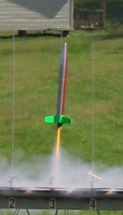
Tao is a 2-stage model rocket that was originally published as an 'Design of
the Quarter' by Estes, and now available on JimZ rocket plans Website. This
unique design incorporates a number of innovative, even radical features. The
main feature is the use of angled tips on the fins of the booster stage to
impart spin during the D12-0 powered boost stage, which 'theoretically'
stabilizes the completely finless sustainer during its flight stage, much like
a thrown 'spiral' football pass. Additional features of this design are a
piston-based wadding-free recovery system on the sustainer, plus a unique
storage hatch which houses a small chute for the booster stage. All in all a
very complex design (at least a Skill Level 3, maybe a 4). My question is would
it work.
Construction:
The components are all pretty standard Estes-style parts, most of which are now
available from other vendors. It requires sections of BT60, BT20 and BT50 body
tubes, three (3) BT60 couplers, a BNC60AH nose cone (available from BMS), 1/8
inch balsa for the fins, four (4) 20-60 centering rings and two (2) 50-60
centering rings, a 1/8 inch launch lug, two small parachutes and other standard
parts.
As mentioned, this is a pretty complex design, but the instructions are very detailed and provide a good step-by-step outline with very nice illustrations. Although there are 15 individual steps, the construction can be summarized in 4 phases; piston/motor-mount construction, sustainer airframe construction, booster motor-mount and airframe construction, and fin construction and mounting. The piston/motor-mount requires a 8 5/8 inch length of BT20 body tube, four (4) 2060 centering rings and a 1" length of BT60 coupler. 2 centering rings and the coupler are used at the top of the tube to create the piston - care must be taken to make sure the piston moves freely within the BT60 airframe, I had to strip off the outer layer of the coupler and sand the centering rings down quite a bit. Do not, at this point, install the other two centering rings. Put the piston assembly aside at this point to dry.
The airframe construction is pretty straightforward. The main thing is the use of another BT60 coupler, inserted about five (5) inches down into the 9 and 5/8 inch BT60 airframe, which serves to block the piston after the ejection charge fires. After this dries, the piston is inserted from the top and the nose cone epoxied into place (I used yellow wood glue which worked fine). Sliding the piston down against the block exposes the bottom (motor mount) part of the piston. The other two centering rings are now installed at the bottom of the tube, serving as a motor mount. They must also be sanded or trimmed to move freely within the BT60 airframe. (Note, the plans call for using a motor hook for engine retention, I found the hook interfered with staging, so I would recommend using a motor block and friction fit for the sustainer engine). Next, drill three (3) 3/8 inch holes at the top of the airframe to allow the ejection gasses to vent. (I only drilled two (2) holes, wanting to blend with my planned paint scheme - more on this later). Lastly, attach a 12 inch chute to a short piece of Kevlar® cord which is tied around the body tube between the motor mount and the piston.
The boost stage utilizes an innovative hatch system to store a small parachute or streamer, which releases when the stage separates. The hatch is created by slicing a section of the airframe (slightly less than 1/3 of the tube) out from between the fins. Because of this, the plans for the booster motor mount must be followed carefully. First, two 5060 centering rings are attached to the BT50 motor tube, then carefully glued to remaining 2/3 of the body tube. Then glue the tube to a BT60 coupler that will be used to hold the two stages together. A system of pins is then installed on the motor mount and hatch which serves to hold the hatch in place during the boost phase. The chute is stored between the hatch door and the motor tube while the stages are coupled together, then released when the stages separate and the hatch comes loose.
The fins are constructed in two pieces attached at a 10 degree angle, then installed on the booster tube with the angled fin tips all facing the same direction to create the spin during the boost phase. One fin is placed opposite the hatch, the other two are just adjacent to the hatch, but on the main part of the tube. The plans recommend using epoxy to attach the fins and small toothpicks under the fillets to provide additional bracing against the torque of the spinning boost phase. Lastly install the launch lug and the sustainer parachute.
Finishing:
After filling the spirals and fins with diluted Elmer's Fill & Finish, I
broke out the spray paint. The plans recommend a three-color paint scheme with
a solid, brightly painted booster stage, then a two-tone upper stage that would
'blend' the colors during the spin phase. I used Krylon florescent green on the
booster stage and a nice silver and burgundy scheme for the sustainer. I
thought it looked nice.
Construction Rating: 4 ½ out of 5
Flight:
The plans recommended a D12-0 for the booster stage and a B6-6 for the
sustainer. The design calls for the B6-6 to fit within the top of the D12-0 to
ensure successful staging. In prepping the rocket I found that I had to do a
bit of sanding at the base of the B6-6 to get it to fit. Also, I could not get
it to fit with the engine hook in place, so I ended up bending it out of the
way. (As mentioned, the hook can be easily omitted for an engine block,
friction fit retention system.)
First (and so far only) flight came at the Pittsburgh Space Command's Fall launch. The engines and recovery systems were prepped (the piston & hatch deployment systems mean that no wadding is required), the recovery systems loaded, the parts coupled together (carefully due to the hatch) and the rocket loaded on the 1/8" rod. Continuity...5...4...3...2...1 and lift off! The boost stage went very well. The spin was noticeable in a slight corkscrewing of the exhaust plume, but it was generally very straight. So far, so good... Things started to go wrong, however, at staging. First, it became obvious that the upper stage was not spinning fast enough for stability as it began to flail about the sky. Fortunately, the flailing was occurring about 300 feet in the air, so there was no risk. Then I noticed the booster coming down without its chute. Finally, the ejection occurred. But instead of the sustainer coming down on its chute, I noticed two separate pieces coming down and not a chute in sight. 'This is not good' I said to myself.
 Recovery:
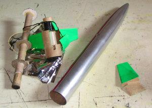
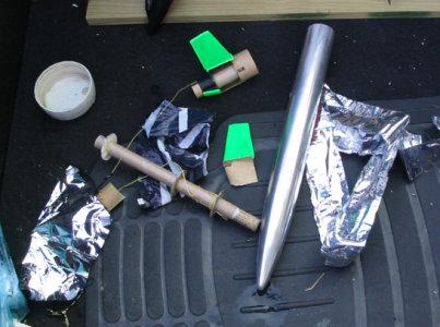
Recovery of the pieces - which took awhile - showed what went wrong. With the
booster, either the spin or the staging shredded the airframe. Specifically,
cutting out the hatch weakened the body tube and caused it to delaminate,
peeling the inner and outer layers apart. I think this is probably an inherent
design flaw - any time you cut the body tube completely you might have this
risk. As for the sustainer, the piston completely blew out of the airframe. I
attributed this to my use of only two, rather than three, vent holes. However,
a contributing factor was the use of fiber centering rings for the piston.
Instead of being blocked by the airframe coupler, they 'bent' around it and
blew right on past.
Flight Rating: 2 out of 5
 Summary:
I was able to recover the pieces and plan to rebuild Tao, with several
modifications. First, I plan to use a 1/8 inch plywood centering ring on the
bottom of the piston for added strength and a thicker coupler to insure that
the piston stops where it is suppose to. I will also be sure to use three vent
holes. Second, I plan to omit the hatch and just go for standard tumble
recovery of the boost stage. (One could try using CA or epoxy on the cut edges
of the boost airframe to strengthen the edges and prevent the delaminating, but
I'm going to go with a traditional tumble recovery) I'm planning reusing the
fins, so I intend to mount them at a 5 to 7 degree angle to vertical, adding to
the 10 degree fin angle for about 15 to 17 degrees of total angle from
vertical. (If I were building new fins, I'd probably increase the angle between
the two pieces to at least 15 and a much as 20 degrees.) This should impart
greater spin during the boost, and hopefully stabilize the sustainer.
Overall Rating: 2 out of 5
 |
 |