McCoy's Micro Wonder Works Bomarc Plan
McCoy's Micro Wonder Works - Bomarc
Contributed by Dick Stafford
| Manufacturer: | McCoy's Micro Wonder Works |
 Brief:
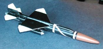
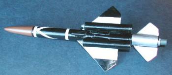
This is a scale model of the Bomarc surface-to-air missile. It flies on MMX II motors and uses streamer recovery. If interested, you can learn more about the Bomarc here.
Construction:
Parts List:
- - Body tube - 10.5mm tube, 6.25" long
- - Fins - 1/64" birch ply and foam picnic plate
- - Nose cone - three strips of 1/8" balsa, 2.5" L x ¾" W, and a short piece of 3/16" dowel
- - Nose weight - section of spent mini motor and lead shot
- - Motor tube - 1" section of plastic pen
- - Centering rings - two ¼" pieces of a spent mini motor
- - Motor block - small piece of a spent MMX motor
- - Ramjets - LOC ¼" launch lug, 1 15/16" long (make 2)
- - Ramjet mounts - scrap balsa ~ 3/32" square x ¾" long (make 2)
- - Intake cones - 3/16" dowel (1/8" exposed) (make 2)
- - Electrical conduit (the bump running along the top of the body) - 3/16" W x 1/8" H balsa strip; 4 5/8" long (3/8" overlaps the stabilizer fin)
- - Launch lug - section of a BiC pen’s ink tube
- - Recovery - 100 lb Kevlar twine and Teflon plumber’s tape streamer
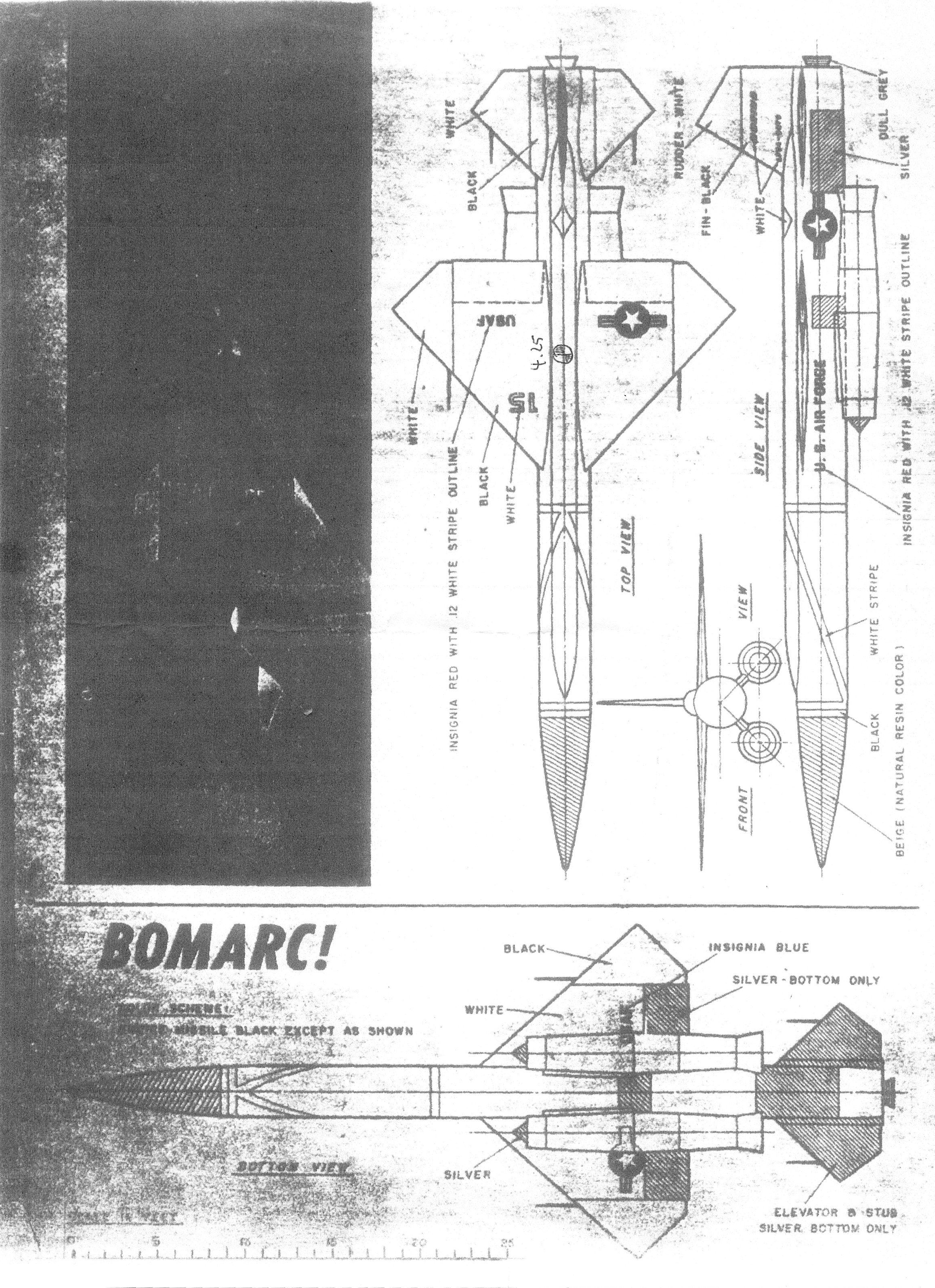
I started with a single sheet plan provided by John McCoy (a.k.a. Micromister on The Rocketry Forum). He provided a hardcopy, which was conveniently sized for 10.5mm tubing. An image of this sheet is provided here (1.5M), but you will have to size it to the right dimensions as you print it. To help in the sizing, you can use the component dimensions in the parts list. In addition, here are the major fin dimensions:
| Fin | Fin Root | Span |
| Front | 1 3/4" | 1 5/16" |
| Rear | 15/16" | 5/8" |
| Stabilizer | 1" | 13/16" |
At John's suggestion, I decided to make the fins from a laminate of foam from a picnic plate and 1/64" Birch ply. I thought that if I made the center foam piece smaller than the Birch layers, that I could glue and clamp the edges to form a sleek structure. I made a copy of the plans and cut out the fin and nosecone templates from that copy.
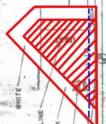 I started with the bigger front fins. I cut two pieces of Birch for each fin, and made a foam ‘fin' that was about 1/8" smaller along each edge, except for the root. The red crosshatched area in the fin diagram (not to scale) depicts this foam section. I also cut about 1/8" off the root edge of the lower birch plate (the blue line in the drawing). Having the lower birch plate smaller helps the fins conform to the body tube.
I covered the components in white glue and clamped the edges with six small clamps. I found that the pressure required to clamp all the edges was almost too much for my small plastic clamps. Thus, this fin took some babysitting until the glue dried. On the next fin, I inset the edge of the foam section by about ¼". This worked better and required no supervision while it set. I repeated this process for the stabilizer. When it came to the small rear fins, I worried that they were too small to flex around a foam core and, with a ¼" inset from the edges, there would not be much foam left. Two layers of Birch did not seem sturdy enough for rear fins, so I added a full sized piece of foam. I am very pleased with how the air-foiled fins came out. They look great, are light, and are very strong. I wish I had tried to make the air foiled shape on the rear fins.
To position these fins, I first marked a centerline on the top and bottom of the tube, and a pair of marks where the fins would intersect the body. I then laid the pair on the drawing, and taped a piece of foam across them. This ensured their relative position was correct. I flipped the pair over, applied some Pro-Bond wood glue, and laid the tube onto them. After the glue had partially set, I lifted it up, checked the alignment relative to the lines on the tube, and then turned it back over until the glue had set. This process was repeated for the rear fins. The top stabilizer fin was added as on any 3/4FNC rocket.
 I couldn't find a scrap piece of balsa to turn the nose cone, so I cut three rectangles from some scrap 1/8" balsa. I cut a section from the middle piece to accommodate a dowel, and glued them together, with the dowel installed. Once it was fully set, I trimmed the corners and turned the cone on a hand drill clamped in a vise. I put a small section of 10.5mm tubing over the dowel to make sure the sizing was right as I went, and used a reverse template to adjust the shape. The resulting cone looks good.
Since I have never acquired any 6mm tubing, I scrounged in my small-parts junk bin around until I found a piece of a plastic pen that fit the MMX motor perfectly. I cut two small pieces from a spent 10.5mm motor casing and trimmed the inside until they fit the plastic tube. I positioned the rear ring so that 1/8" of the motor tube hangs out the back, to simulate the nozzle on the plan. I also notched the front ring so the thin Kevlar® twine tied to the motor mount would pass through. I glued the centering rings and the Kevlar twine to the tube using leftover epoxy from another job, along with a small chunk of a MMX motor casing to serve as a motor block.
 I made the Ramjets from LOC ¼" launch lugs and turned the intake cones from 3/16" dowel. They are a little less than ½" long with only the front 1/8" exposed. I trimmed some scrap balsa to make the stand-offs and positioned the using the full sized plans and my eyeballs.
I found some 3/16" x 1/8" balsa stock and cut a 4 5/8" section for the electrical conduit that runs along the top of the rocket. This was shaped by hand, and a notch was cut out to let it slide over the rear stabilizer. (I messed up and made it about 1/8 too short, an error that wasn't noticed until is was glued on).
Micromister also provided the CG for a stable Bomarc, and I scaled that measurement for this model. It turned out that the CG should be 4.25" from the tip of the nose. Mine was way off - hmmm, how to add weight to this small balsa cone? I decided to add a section of motor casing to the nose cone's shoulder and epoxy in some lead shot. I left about 1/8" of the dowel hanging out of the balsa cone, which served to align the casing with the shoulder. I cut a ½" piece of casing, trimmed the outer paper, added some lead shot, and capped the end with tape. The CG was now about right, and I took the model to the post office to weight it. It came in at 0.50oz (14.17g), which should make for a low flight. I then set the lead shot and the twine in some epoxy, and attached the nose weight assembly onto the cone.
I approximated the scale color scheme presented on the plans. I started with white primer, and then masked and hand-painted the black, silver, and brown areas. The stripes on the front were made with thin strips of white label material (adhesive paper). I haven't come up with any decals.
Flight:
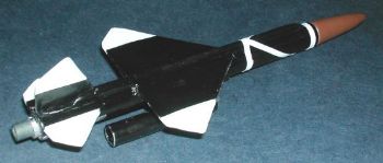
I used a 12" piece of Teflon plumber's tape as a streamer and a small ball of tape as wadding. GSE included the guts of a stock igniter, my Pratt GO-Box, and the rod from the MicroMaxx starter kit. The microBomarc flew off sideways, attaining an altitude of about 5 feet before impacting the side of my SUV.
Summary:
On the plus side, this is a nice looking semi-scale model of the Bomarc. The composite fins turned out very nicely and I will consider this technique for other models.
On the minus side, it is too heavy, but the motor mount and ramjets could both lightened. I want to avoid adding more nose weight if I can. Since the trajectory was straight, if not in an upwardly direction, I will try it again with a longer, stiffer rod.
 |
 |