 Brief:
I wanted to make something to fly in the scale contest at the IRW 2003, and I
only had a week to do it in. I was very intrigued by the recent 10...9...8...
article detailing a Plastic Model Conversion (PMC) by Steven Rogers. Lastly,
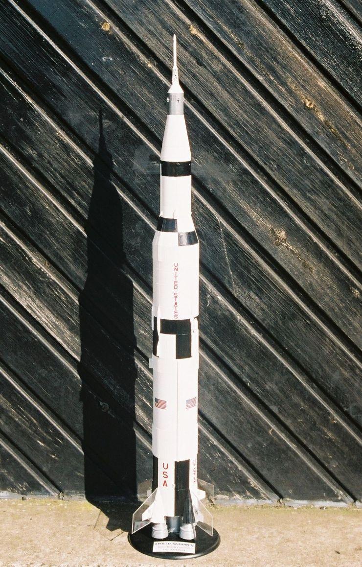
there were two Airfix 1/144th scale Saturn V kits peering out of a bag in the
corner of the "spare" room. These had been bought several years ago
when Woolworth's were selling them off for less than a tenner each.
Hmmm, the theme for the IRW scale contest changes every year, and this year it was "manned boosters", so the Saturn V would fit, but it also suggested the Cosmodrome Vostok kit peering at me from another corner of the room. However, that particular kit is rather more than a week's worth of building! For me, anyway. So, unless I built something from scratch, that made the Saturn V favourite again.
Construction:
There were a few compromises:
- I had originally bought the two Saturn V kits with the intention of
building one for display, with the possibility of converting one for flight. Of
course, once I started to think about how I might go about it, my imagination
ran wild. What motors should it be built for? Naturally, my first inclination
was to power all three stages: 5 x 18mm in the S-IC (first stage), 5 x 13mm in
the S-II (second stage) and a 13mm motor in the S-IVB (third stage). Just as
naturally, I discarded this idea when I considered what I would do for fins on
the upper stages. A bit of googling revealed that this had been done before,
but the folding fins mechanisms were beyond me in the time available.
- I googled widely and consulted various email lists including
pmc-rockets@yahoogroups.com where I found some good advice. Eventually I
decided to keep it simple and go with a single motor mount. That made the motor
mount size a no-brainer too. Rocksim was telling me that an 18mm motor wouldn't
be enough (even a composite D would be borderline) and so it had to be 24mm.
Rocksim also had some interesting things to say about the first stage fins. It
was quite easy to develop a simple model in Rocksim, and it showed that with a
little nose weight the model would be stable even with scale sized fins. You
can download a copy of the
Rocksim
file here. However, that additional nose weight would also increase the
motor power required. At this point I still thought there was a chance of being
able to fly on an Estes D, so I wanted to minimise the weight.
- Recovery was another issue that need some careful thought. I suppose the obvious thing to do would have been to run a stuffer tube the full length of the stack and use the Command & Service Module as the nose cone. However this would have meant putting quite a lot of work into centering the stuffer tube, so I opted to split the model at the stage 1 / 2 join. Given that basic design, I thought it best to recover the two halves separately on independent parachutes. I'll go into the detailed arrangement later, suffice to say that the main work in this conversion is running a motor mount / stuffer tube through the first stage.
These construction notes should ideally be read in conjunction with the
instructions that come with the kit.
A
scan is available here. I also submitted this scan to Sven Ninfinger's web
site http://www.ninfinger.org/ some
time ago, so they may have been uploaded and available there by now. For those
unfamiliar with the Ninfinger site, it's a huge resource covering both model
rocketry and scale space modelling. In the following paragraphs the numbers in
parenthesis are the actual part numbers.
Step 1
 Add the conduits to the
fin can, but omit the fins. The fins from the kit are not used, but one is
needed to be used as a template. I used clear 1mm thick Lexan to make larger
replacement fins. Using one of the original fins I scribed the outline and
painted on the pattern of the original fin. The new fins had tab matching the
original fins. I found them to be a tight fit, so simply push fit rather than
glued them into place. After trying them out, I removed them until after final
painting.
Add the conduits to the
fin can, but omit the fins. The fins from the kit are not used, but one is
needed to be used as a template. I used clear 1mm thick Lexan to make larger
replacement fins. Using one of the original fins I scribed the outline and
painted on the pattern of the original fin. The new fins had tab matching the
original fins. I found them to be a tight fit, so simply push fit rather than
glued them into place. After trying them out, I removed them until after final
painting.
Step 2
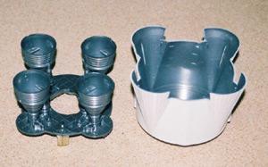
 Cut off the mounting studs from the booster fin can
(5) and the engine mounting plate (18). The stud can be cut from the plate with
an x-act knife. The stud on the fin can may be broken off manually.Cut a hole
to suit a BT-50 motor mount tube in both the fin can and the plate. This is for
the motor mount/stuffer tube. Assemble the outer nozzles as shown and fit to
the baseplate, omitting the centre nozzle. Spray the nozzle base plate
assembly, and the inside of the fin can silver.
Cut off the mounting studs from the booster fin can
(5) and the engine mounting plate (18). The stud can be cut from the plate with
an x-act knife. The stud on the fin can may be broken off manually.Cut a hole
to suit a BT-50 motor mount tube in both the fin can and the plate. This is for
the motor mount/stuffer tube. Assemble the outer nozzles as shown and fit to
the baseplate, omitting the centre nozzle. Spray the nozzle base plate
assembly, and the inside of the fin can silver.
Glue a small wooden block to the back of the nozzle plate and allow to dry. Drill a small pilot hole through the nozzle plate and into the wooden block. Run some thin CA into the hole and then screw in a small eye hook. This is the parachute attachment point for recovery of the first stage. Don't glue the nozzle plate assembly to the fin can yet.
Step 3
Spray the inside of the first stage halves silver. I used some metallic silver paint from B&Q.
At this point I should admit that I didn't really pay attention to the colour of the innards of the stages, or even the aft ends and engine bells. If I had, I would have noticed that silver isn't really appropriate! You can see what I mean by taking a look at these photos of the Saturn V at KSC - http://www.nsrg.org.uk/outings/ksc/saturn/. I took these pictures when I went to see the last Columbia launch in January 2003 - http://www.nsrg.org.uk/outings/ksc/saturn/.
Open up a hole in the first stage forward tank bulkhead (19) for the BT50 motor mount. Cut a length of BT50 310mm long, this is used for the motor mount / stuffer tube. Us a short piece of coupler tube, or a slice of a spent Estes D motor as a thrust ring. At this point I should also have added a motor retaining hook, but I forgot. More of this later!
Although I chose to use the forward tank bulkhead as the centering ring, I didn't glue it into the place directed by the instructions. I put it about mid-way up The first stage. This leaves much more room for parachutes. The two halves of the first stage (20,21) are then assembled and glued to the fin can. Next slide in the motor mount / stuffer tube, but don't glue it in place yet. I chose to paint this before assembly, as it's much easier. Dry fit the engine mounting plate and nozzle assembly from step 2. This allows accurate positioning of the stuffer tube. The end should be level with the ends of the four nozzles. Carefully remove the assembly, glue the stuffer tune in place and replace and fix the nozzle assembly. Having the motor mount level with the end of the rocket nozzles means that they can be left on for flight. Just arrange for the exhaust of the real motor to be deflected away form the base of the rocket! Glue on two short lengths of launch lug, one at the top of the body, one at the base.
Step 4
Assemble the interstage as directed and spray the inside silver. Although it's designed to be removable, I glued the interstage to the first stage because, as with the location of the forward tank bulkhead, it leaves more room for the parachutes.
Step 5
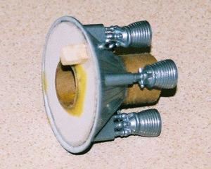
Open up a hole in the second stage aft bulkhead (27) to take a length of BT50 coupler. Cut a length of BT50 coupler 45mm long. Cut a thick card or balsa centering ring 60mm in diameter to centre the BT50 coupler. I used card. It doesn't really have to be very strong, it's more of a guide than anything.
Cut two small block of wood and glue one the back of the back of the aft bulkhead, and one the inside of one of the body halves. Drill two small pilot holes and screw in eye hooks suing CA as before. It is important to make sure these hooks will be in line when all the part are assembled.
Push fit the engine nozzles onto the aft bulkhead, but don't glue yet. Stand the part on the nozzles, and insert the length of BT50 coupler into the hole in the bulkhead, but don't glue it in place yet. Slip the centering ring over the coupler and The within the forward part of The bulkhead, making sure that the end of the coupler is square with the ends of the motor nozzles. Glue the centring ring into part 27. Let it dry.
Cut a small bulkhead from balsa or thick card and use it to plug the end of the coupler. The protruding length of coupler will fit into the BT50 stuffer tube on the first stage. Assemble the rest of the second stage as directed, but omitting the centre motor nozzle and it's mounting (26,30,31). With a sharp knife, Remove the small studs in the inside of the base of the second stage body. These are meant to "twist lock" the second stage to the first stage, but as this is where the rocket will split at ejection, this would now be a Bad Thing (TM).
Step 6
Assemble the third stage as directed, but omit the engine nozzle as it won't be visible. Glue this stage to the second stage after painting.
Step 7
Skipped assembly of the Lunar Module as it won't be visible in the completed model.
Step 8
Omit the Lunar Module from step 7 and glue the adapter ring (61) and LM shrouds (62, 63) in place. I didn't bother to paint the interiors, as they are not visible when glued in place.
Step 9
Build the Service Module as indicated, but you can omit the nozzle (68) as it isn't visible when the model is completed. Although it is designed to be removed, I glued the service module to the LM housing, after final painting to avoid losing it.
Step 10
Stage 10 is the assembly of the command module. Since the command module isn't visible when assembled, this stage can be omitted entirely.
Step 11
Complete stage 11 as directed, apart from the command module that wasn't built in stage 10, paint the assembly white and glue the boost protective cover to the service module.
Step 12
Omit the nozzle adapter (79), instead glue a spent 24mm motor to the stand. This will fit into the BT50 tube of the motor mount and allow display of the completed model.
Finishing:
Some of the painting I did as I went along, but I left the final painting until most stuff was assembled. I masked off the insides of the first, second and third stages, using rolled up paper. I painted them all over using a couple of coats of Halford Diamond White. The plastic seemed like a good surface, so I skipped applying a coat of primer.
I did consider masking around the black roll patterns and spraying them on too, but I always find masking to be a little tricky, and fitting the tape to the surface corrugations was a bit daunting.
In the end I used a paintbrush and Humbrol Satin Black enamel. OK, so up close you can tell I applied the paint by hand, but from a distance I reckon it looks acceptable.
Of course I discarded the Airfix painting directions, as they are for a test article rather than any of the manned boosters. Everyone knows that, right? So I took my painting directions from Peter Alway's excellent "Rockets of the World" (ISBN 0-9627876-7-1 - a must for every Space Modeler's book shelf). Having said that, I did cheat a little. Because I was applying the paint by hand, I decided to take liberties with the positioning of some of the black/white painted edges to places more convenient for my aging Mk1 eyeballs. I leave determination of the location of these liberties as an exercise for the reader.
Decals
The Airfix decals are OK, in the main, with a couple of exceptions. The red
decals, "USA" & "UNITED STATES" are fine, as are the
black & white fin letters and targets, but the Stars & Stripes are
terrible. The blue and white star field is out of register with the red and
white stripes. I fixed this by cutting out the star fields and applying them
separately. The same problem occurs on the much smaller Stars and Stripes for
the Service module. Having got this gripe over, I have to admit that the decals
were nice and thin and conformed well when applied to raised detail.
Recovery Rigging
Parachutes. I love hemispherical parachutes and loved the idea of my rocket
dropping from the sky on proper red & white parachutes. There are several
tool on the internet for generating templates for the gores. I used the one on
Richard Nakka's experimental rocketry web site. This generates pattern to
produces a semi-ellipsoid shape, which looks like a slightly flattened
hemisphere. It's meant to be more efficient, but I would guess it's hard to
tell at these dimensions. I made both parachute with gores 250mm across the
bottom, with six gores per parachute. The gores were cut from nylon, and my
ever support full wife, Karen, stitched them together for me.
The parachutes are both housed inside the first stage. The first stage parachute within The stuffer tube, and the parachute for the second/third stage assemble around the outside of the stuffer tube.
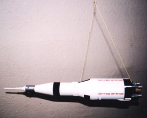 My original idea was to have separate
parachutes for the first stage, and the rest of the rocket, rigged to bring
them down horizontally. That is exactly what I did for the second/third
stage/CSM assembly. I attached a length of Kevlar approximately 600mm long to
the previously installed eye hooks. Holding the model up by the Kevlar I
arranged for the rocket half to be suspended horizontally, and tied a loop
where I was holding the Kevlar. This is there the parachute shroud lines were
attached to.
My original idea was to have separate
parachutes for the first stage, and the rest of the rocket, rigged to bring
them down horizontally. That is exactly what I did for the second/third
stage/CSM assembly. I attached a length of Kevlar approximately 600mm long to
the previously installed eye hooks. Holding the model up by the Kevlar I
arranged for the rocket half to be suspended horizontally, and tied a loop
where I was holding the Kevlar. This is there the parachute shroud lines were
attached to.
For the first stage, I started having second thoughts. I only had one solid
parachute attachment point, at the base for the stage. The intention had been
to have another attachment point inside the stuffer tube. However the stuffer
tube is unsupported for 110mm of it's length, and it seemed likely that this
would crimp when hanging from the parachute. I tried to rectify this by fitting
a "fillet" of balsa between The body wall and stuffer tube, changing
the surrounding space from an "O" shape to a "C" shape, but
I still wasn't satisfied. In the end I reasoned that this stage needn't be
recovered horizontally as all of the fragile detail was at the rear end. So, I
used a single parachute attachment point, running a length of Kevlar up the
side of the rocket and into the parachute bay via a small notch in the stage
body.
 Flight:
It was when prepping The rocket for flight that I realised I had left off any
method of motor retention. I could have sworn that I had fitted and engine
hook, but alas, no. As launch fever gripped me, I casually applied some tape
around the end of the RMS. It's hard to believe that I really thought this
would be sufficient. It wasn't.
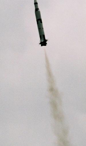
The launch was excellent, with a reasonably straight boost, but there was no ejection at apogee. It looked like we were going to see a classic lawn dart, but the rocket became horizontal and began to spin. I've seen rockets recover like this before, notably the Estes Phoenix. Upon examination, it was seen that the motor had not been retained and had in fact been kicked out at ejection. Lots of people helped search for the RMS casing, randomly at first, but then I think it was Mike Crewe who suggested forming a line and walking the area methodically. I think John Bonsor was the one to find the casing. Many thanks to Mike, John and everyone else that helped with the search.
The rocket itself was in surprisingly good condition. All four fins had come off, as had the Escape Tower and the third stage, but it was all repairable. I just need to retrofit some positive motor retention and I'll be ready to fly again.
As for the contest, well, despite the damage, I won joint first prize, shared with Mike Crewe and his Estes Mercury Redstone. We both won Estes Big Bertha rocket kits, which we're going to drag race at next year's event.
Summary:
A very slightly different version of this article was published in volume 7
issue 4 of 10...9...8... the newsletter of the United Kingdom Rocketry
Association.
 |
 |