Scratch Transonic Original Design / Scratch Built
Scratch - Transonic {Scratch}
Contributed by John Chapman
| Manufacturer: | Scratch |
Brief:
This is a maximum strength midpower rocket that still incorporates wood and
plastic construction. It will handle any 24mm motor, as well as most dunkings
in water.
Construction:
This rocket uses 1.1 in. phenolic airframe tubing topped by the PML Urethane
nose cone - the only commercially produced cone that fits this tubing. Between
3/32 ply fins and TTW construction, this rocket is practically indestructible.
TTW construction and phenolic tubing require a complexity not typical with low power rockets. I used a Dremel spiral saw to cut the fin slits (3) in the 1.1 phenolic tubing. The motor mount was constructed with epoxy and centering rings to mount the Estes 24mm tube in the appropriate position for TTW fin mounting. I used a long E motor hook as part of the mount. I used 100 lb. Kevlar® thread epoxied through the motor mount as a parachute connection. Indeed, epoxy was used in virtually the entire thing.
After the motor mount assembly dried, I put it in place, and used the slots to trace the fin footprints onto the engine tube. I cut thin stringers of balsa, and CA'ed them in place right next to the footprints, bounded on the top and bottom with a centering ring. The effect was intended to have the advantages of internal fillets, without the difficulty of applying them through such a tight space between the tubes. This worked like a charm.
I used the Rocsim fin template guide to generate the correct template for the TTW mount. I then cut the fins from 3/32 in. plywood. After trying the spiral saw, I went to a power jigsaw, which did a far better job. I gang sanded the fins to uniform dimensions, and then beveled the leading edge to a sharp cross section. The wood grain also looked "sharp", with the darker plywood core providing a nice contrast. The trailing edges were beveled, but not quite sharp.
Because I used five minute epoxy, the next steps were hurried. I mixed up a batch, and used a chopstick to smear it within the airframe, in the right place to bond with the front centering ring on the engine mount assembly. A second layer was put ahead of the trailing centering ring, as the first ring cleared the aft end. The last centering ring was epoxied in place indexed with the "notch" cut though the ring to leave room for the motor hook to flex. I was sure to make the slots line up correctly.
I then epoxied each plywood fin in place, using enough epoxy to blob up to fill the fin slot close to level. To keep from dripping epoxy, I needed to mix separate small batches of epoxy for each fin slot.
Next came the smoothing operation using Elmers wood thinner thinned with water, and sanded after each coat partially dried. The fillets at the base of each fin were also done using this material and technique, since the epoxy, plywood and phenolic TTW combination makes it impossible to even flex the fins. The fillets were for looks and aerodynamics only.
Since the combo could theoretically take a G engine, I wanted to be sure the launching lug was big enough. I used an aluminum 2013 arrow shaft cut to length, and angled by cutting the front edge to a wedge shape. I glued it in place and filleted it in place with epoxy. I can use a 1/4 in. welding rod for larger size engines.
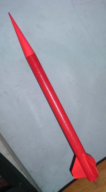
I had recently built my first "girl rocket" for my daughter, and marveled at the visibility provided by the hot pink fluorescent paint. After filling the spirals in the tube with Elmers filler, I sanded, painted, and then clear coated. To add a bit of shine and smoothness, I used floor wax to finally coat the surface.
I added a couple feet of elastic to the already long Kevlar® cord, and hooked a 12" nylon chute to the nose cone with a fishing swivel and snap rings. Later testing suggested this was not enough chute.
Flight:
The maiden flight was to test low speed stability, and recovery. I did not want
to blast the school athletic field with an F right out of the starting gate. I
built and installed an 18-24mm engine adapter, and installed a C6-5. I launched
it off a 3/16 launch rod.
Well, it was pretty normal at first. The rocket was stable, but then nosed over and kept going after burnout. The delay was way too long, and that may have been the engine, since rocsim says it should have been good. Fortunately, the chute deployed in time, and there was no lawn dart nor core sample. For small engines, I'd want the shortest delay possible.
The engine hook picked up a bit of dirt from the grass. It hit with a bit more force than I'd like, but no damage was done. Still, I will use at least a 15" chute next time - probably an 18, to protect the motor hook.
PS: The 18mm adapter blew clear - no impact on recovery deployment.
Summary:
Pros: Bombproof and tough. Able to handle almost any ridiculous engine you can
cram into it. Probably able to lawn dart from 300 feet up into sod without
damage. Easy to see, and teaches you lots about tough construction. A
"girl rocket" on the outside, that is all steroid - induced toughness
on the inside.
Cons: Complicated to build, and expensive. Not for novices. Heavy, and could cause more damage than a light rocket if the chute failed. Needs a big chute. Limited nose cone options.
Other:
The Elmers goop is the key to smoothness. TTW / epoxy / phenolic is so strong
it is scary. The world needs a good, LIGHT, 1.1 in. nose cone (PML is good but
HEAVY).
Sponsored Ads


 | Intermediate Rocket Kit | Step-by-Step Instructions | Science Education Kits | Great for Teachers, Youth Group Leaders and Birthdays,Blue")


, Launch Pad/ Controller, Glue, Four AA Batteries, and Two Engines")
 |
 |