| Manufacturer: | Scratch |
Brief:
The Thorn is a complex futuristic single-stage rocket intended for RMS 18mm D
motors. It is 30" tall with BT-70 (2.2in) maximum diameter and weighs 5
3/8 oz unloaded.
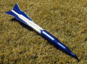 My design of
Thorn was motivated by two factors. I sought a design where nearly the whole
rocket had the boat tail effect of slimming toward the aft end. Further, I had
been interested in offset or canted transitions, and had worked hard to create
the offset transition shroud template tool mentioned
in a
thread on The Rocketry Forum. I also owe a debt to Bruce S. Levison, who
helped me with a RockSim file for this design. As you can imagine, coping with
these canted transitions in RockSim was a nightmare, but Bruce is an expert!
My design of
Thorn was motivated by two factors. I sought a design where nearly the whole
rocket had the boat tail effect of slimming toward the aft end. Further, I had
been interested in offset or canted transitions, and had worked hard to create
the offset transition shroud template tool mentioned
in a
thread on The Rocketry Forum. I also owe a debt to Bruce S. Levison, who
helped me with a RockSim file for this design. As you can imagine, coping with
these canted transitions in RockSim was a nightmare, but Bruce is an expert!
Construction:
Reading nose to tail, the rocket includes:
- conical nose for BT-20
- BT-20 tube
- centered balsa transition BT-20 to BT-60
- BT-60 tube
- centered balsa transition BT-60 to BT-70
- BT-70 tube
- transition shroud from BT-70 to 3xBT-50
- 3 BT-50 tubes
- 3 canted transition shrouds from 3 BT-50s to 3 BT-20s with maximal offsets toward centerline
- 3 BT-20 tubes
- transition shroud from 3 BT-20s to 1 BT-20
- BT-20 tube
From my scratch building perspective, the most interesting parts of the construction were the slimming transitions in the aft portion of the rocket. The top one, from BT-70 to three BT-50s was easy. Three BT-50s were glued in a 3 BT-50 centering ring for BT-70. This was then inserted in the BT-70 with the centering ring flush with the BT-70 bottom and about 1.25 inches of 3 BT-50s inside the BT-70. The clustered tubes fit almost snugly in the BT-70, so additional glue can cement the inner tubes to the inside wall of the BT-70. Cardstock shrouds were constructed by trial and trimming for the final look.
The next transitions were canted. A BT-20 was laid inside (with 1.25 inch overlap) each BT-50 so that the two tubes touched at the nearest possible point to the rocket centerline. The cardstock shrouds were drawn with my software. The shroud is plumb vertical nearest the centerline and canted most on the opposite side.
The bottom transitions were also canted. First, I slotted the 3 x BT-20 assembly so that another BT-20 could be inserted, centered, several inches up the middle of the 3 x BT-20 cluster. Extra strong fillets were needed here. Next, I used my software to make 3 canted transitions from BT-20 to BT-20. They are canted because the centerlines are offset with the bottom BT-20 centerline matching the centerline of the rocket. These three transition shrouds all intersect since they are all transitioning to the same single BT-20. I "guesstimated" the curves of intersection and trimmed until I achieved a good fit.
One construction gotcha occurs at each place where there are shrouds. Ejection gasses should shoot up the rocket body but might eject downwards and out through any shrouded area, possibly even bursting the shrouds. Therefore, I closed off all such tube ends using glue, leftover CR fiberboard, and other stuff. This ensured that the gasses can only go up and out the nose.
Another gotcha was the engine hook. The tail is 18mm minimum diameter, but I hate to risk my RMS casing with a loose friction fit. I also hate damaging my rockets/casings trying to remove a tight friction fit so I filed a standard hook to leave room for the ejection charge and epoxied it to the outside of the rocket. I smoothed the wet epoxy with gloves and rubbing alcohol to get a smooth, subtle bubble shape over the hook, leaving the bottom portion free to flex. The result is not conspicuous at all.
The third gotcha was the launch lugs, which by some miracle I actually remembered to attach during construction. The contours of this rocket make placement difficult. I put one lug on the thickest BT-70 part of the body. The other was placed on the surface of one fin. Alignment was ensured by using an actual launch rod.
The fins were 3/32" balsa. Each fin was built from 3 portions glued together to get the grain aligned favorably. Some custom trimming was needed on each root edge to get it to snugly fit the changing shape of the body.
Swing testing was a bit doubtful at first. The rocket didn't snap to a stable position immediately, but after eventual stabilization it stayed stable. I added 0.25oz nose weight in the top payload compartment to be confident. Space in the chute compartment is extremely limited. I used a 24" chute and a 4" square of Nomex® with elastic and Kevlar® thread for the shock cord and shroud lines.
Finishing:
I experimented with various methods for finishing the transitions. It seemed
that the best method was to begin with a coating of CA to make the cardstock
more waterproof then coat them with diluted Elmer's Fill 'n' Finish. I sanded
until smooth, primed, and did it all again until I was satisfied. When I
skipped the initial CA coating, I had problems with the cardstock warping under
wet F'n'F.
Paint was Rustoleum metallic blue and Krylon silver. Top coating used Krylon clear. Unfortunately, my hard work was partly spoiled during painting because I was rushing to make a planned launch date and had bad problems with the masking peeling off fresh paint flakes. I patched it up as well as I could, but the result was messy.
Flight:
Finally it was time to load up a AT RMS D13-4 and launch. Boost was straight
with perhaps a very slight spin. Ejection was slightly early at maybe 800 feet.
Two more D13 flights at Mile High Mayhem were equally good, maybe a bit higher.
Thorn definitely got a number of curious looks at MHM--people were interested
in the unusual design.
Recovery:
Recovery on the first flight was fine, although at first I thought the Nomex®
pad was a flapping fin. One fin suffered non-breaking wrinkle damage on a
landing too, but I'll just paint over this and keep flying.
Sponsored Ads


 | Intermediate Rocket Kit | Step-by-Step Instructions | Science Education Kits | Great for Teachers, Youth Group Leaders and Birthdays,Blue")


, Launch Pad/ Controller, Glue, Four AA Batteries, and Two Engines")
 |
 |