| Manufacturer: | Clone |
 Brief:
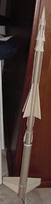
Single stage parachute recovery scale model rocket.
Construction:
- 1 BT 55 10.5 in.
- 1 BT 50 18 in.
- 1 BT 20 1.5 in.
- 1 BT 50 5 in (engine mount)
- 1 TA2050 transition (2 in long)
- 1 BNC20N nose cone
- 2 1/8 x 1/16 x 36 in wood strips
- 5 50/55 motor mount rings
- 1/8 in lite ply
- 3/32 balsa
- 2 1 in. x 3/16 launch lug
- 36 in x ¼ elastic shock cord
- screw eye
- .5 oz nose weight (lead shot)
- 16-18 in parachute
- “E” engine hook
- engine block
- Kit instructions from JimZ’s
The parts were assembled following the downloaded instructions. The assembly is complicated and I will not attempt to go into each step here. 20 minute epoxy was used on the subassemblies, and CA on all fins. I used 1/8 lite ply for the larger upper and lower stage fins, and 3/32 balsa for the smaller fins and the upper stage supports. This is due mainly to personal preference. A 24 mm motor mount was fashioned from the 5 inch BT50 tube, engine hook, engine block, and 2 50/55 centering rings, and substituted for the 18 mm motor mount. Alternately, a 25 inch section of BT 50 could be substituted for the separate motor mount and upper stage assembly. This would make a stiffer rocket.
The lower stage has three large fins built in two halves and epoxied together. There are three supports linking the upper and lower stages and the rest of the upper stage is a four fin assembly, with four wood strips between the three sets of upper stage fins. All bare wood was finished with traditional sanding and sealing methods. During assembly care must be taken to align the fins both to the tubes and in relation to the whole rocket. The three fin/four fin positional relationship is very specific in the instructions.
The nose cone and transition were purchased from BMS and required final fitting and, of course, sanding and sealing. The .5 oz nose weight was epoxied into the BT 20 tube between the nose cone and transition. The screw eye was screwed into the transition and CA’ed into place and the shock cord was attached to the eyehook on one end and a customary three fold mount on the other. I will use a homemade 16 in. mylar chute for this, as I prefer the smallest possible safe chute. An 18 in. prefab chute could be used. The plans call for a special fiber ring above the three upper stage support brackets. This is the equivalent of a 50/55 centering ring. I was unable to fabricate this to my satisfaction, so I substituted a 50/55 engine mount ring, which is thicker. Care must be taken when placing the wood strips to ensure that they align at the BT 50/transition joint. I used spruce strips instead of balsa due to the hardness of the wood. Spruce is still flexible enough to bend to the contours of the transition and nose cone. Mine turned out to be 11.5 in. long on the body tube and 4.5 in. long on the transition/nose cone. The plans call for paper strips to be placed around the first stage at two points. I used self-adhesive computer label paper and a rotary paper cutter to fashion the strips. The launch lugs were placed on pieces of the wood strips to keep them off the lower stage wraps. I also used a fin alignment tool that I downloaded to make extremely accurate alignment patterns. I found the ones with JimZ’s plans were slightly off. I have to paint outside, so the rocket was not finished due to frigid temperatures. This will have to wait till spring, I’m afraid.
Flight:
This rocket was put into RocSim 6 as accurately as I could manage. It was simulated on a C6-3 to 385 feet, D12-5 to 707 feet and E9-6 to 1323 feet, all stable and safely recovered on a 16 in. chute. It will be flown IRL when the wind chill climbs at least slightly above “bone numbing.”
Summary:
This rocket is somewhat difficult to build properly due to all the various alignment issues. I have a fondness for scale military, and I had wanted to build this as a kid almost 25 years ago. I would not have had the skill or patience then. I upgraded to a 24 mm engine mount due to the weight of this model. It was a very easy upgrade.
PROS:
Easy availability of fairly common parts, except one ring. Great scale appearance.
CONS:
Alignment issues. Uses lots of sandpaper and elbow grease finishing all those FINS!
Other:
I made the "E" hook from the metal strip in a windshield wiper blade, heated with a torch and bent with pliers. In hindsight, I would build this in two halves and paint them separately, then slide them together. I would also probably use one 25 inch BT50 for strength.
Related Products


 |
 |