Descon 9 TRI-STOMP Original Design / Scratch Built
Scratch - TRI-STOMP {Scratch}
Contributed by David Fergus
| Manufacturer: | Scratch |
TRI-STOMP
by David Fergus
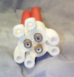
 TriStomp Family |
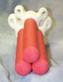
 Forward View |
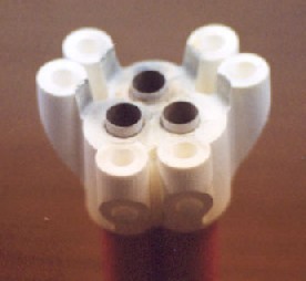
 After View |
Design Summary:
A derivative of the classic foam air powered rocket, this 3.4 oz. missile is a 3-engine cluster foam rocket flown on three 18mm engines with BOINK (bounce on impact, no kidding) recovery. A bit of something different!
Concept Development:
The Minnesota Amateur Spacemodeler Association (MASA) rocketry club has been proliferating these red foam rockets for years, but only as a single engine boink rocket. Recently, 2-stagers have begun to appear at club launches. This design represents an escalation of thrust and weight in the stomp wars. The photo of the stomp family includes an original single engine model, a 2-stage streamer recovery model, and the TRI-STOMP. The TRI-STOMP also owes it's concept design to a rocket observed by the designer several years ago consisting of four Big Berthas put together into one rocket and flown on a cluster of four 18mm engines.
Materials:
Obtain three Mark 1, Mod 0 air-powered Stomp Rockets.
Other materials and tools needed:
Three 2.5î lengths of BT-20 tubing
Three 18mm engine blocks
One 2" length of 3/16" launch lug
Masking tape
1.5 oz. of lead shot or BB's
hobby knife
needle nose pliers
Carpenter's glue
30 minute epoxy
Construction:
1. Glue the three thrust blocks flush into one end of the three motor mount tubes. Set aside to dry for a few minutes.
2. Using a hobby knife or a 3/4 inch diameter brass tube or conduit, cut out the forward end of the center of the white foam fin units. The hole needs to be just large enough for the motor mount tube to fit through and centered. Note that the standard air-powered foam rocket does not have the white fin unit permanently attached to the red foam body, but only relies on a friction fit.
3. About 1/2 inch up from the bottom end of the motor mount tube (the opposite end of the thrust block), wrap a ring of masking tape to a thickness that corresponds with the diameter of the hole in the white fin units. This ring of tape serves as a centering ring so it should be snug.
4. Again, using a hobby knife or a 3/4 inch dia. metal tube, hollow or ream out a round hole in the center of the bottom of the three red foam bodies. This hole should be about 1/2 to 3/4 inch deep. A needle nose pliers works well to remove foam material after the cut has been made.
5. Using a hobby knife, cut a wedge shape out of the red foam bodies near the nose of each. This step should be done one body at a time to keep from getting the wedges mixed up so they will fit flush after adding the nose weight. Using a needle nose pliers, pull out chunks of foam to create a hollow chamber inside the foam body. This chamber needs to be large enough to accommodate 1/2 oz. of lead shot or BB's. Pour in the lead weight, mix a batch of epoxy and stir it into the BB's, then epoxy the wedge shaped hatch back over the cavity. It should be hard to see when done. Repeat this for the other two red foam bodies.
6. Trim off one fin and extra fin unit material from the white fin units using a hobby knife or razor blade so that the three units will fit together in a tri-pattern and the red foam bodies when inserted into the fin units will be flush with each other. Refer to the two front and rear views to see how this should look when assembled.
7. For each of the three rockets, smear liberal (but not so much that it will end up where the motor goes) amounts of 30 minute epoxy or Carpenter's glue into the bottom of the red body, the cavity of the white body where the red body fits, and inside the cavity where the motor mount tube fits. Push all three parts (motor mount tube, red body, fin unit) together and hold while the epoxy sets. The motor mount tube should be about 1/2 inch out of the back of the white fin unit. Put an expended motor into the motor mount and move it in and out several times to ensure there is no extraneous glue in the motor mount tube that when dry would hinder the motor from fitting flush against the motor block. Clean that glue out if necessary before it sets. Repeat for the other two rocket bodies.
8. Epoxy the three rocket bodies together. Hold while the glue sets.
9. Epoxy the launch lug into one of the crevasses between the fins.
Flight Prep:
Recommended motors are any A, B, or C motor. Any delay from 0 to 7 is also fine. Experimentation is recommended to achieve the effect most desirable for you. The motors should only be friction fitted enough to keep them from falling out during prep and pad loading. The rocket is designed to eject the motors when the ejection charges fire. Caution should be used to ensure the ejected hot motors do not start a fire in dry grass or other flammable material.
Flight:
The TRI-STOMP has flown on B6-4s and B4-4s so far. A typical flight profile whenever a stomp rocket flies is the whoosh of the engine, the pop of the ejection charge and bounce recovery near the pads. For a TRI-STOMP, sound effects are magnified by a factor of three as all three engines pop out and not usually at the same instant. Spectators had comments such as "Wow!", "Cool!", and "Fireworks!".
click to enlarge
Recovery:
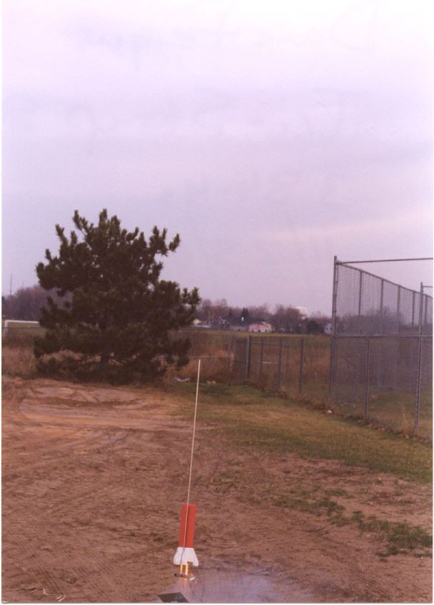
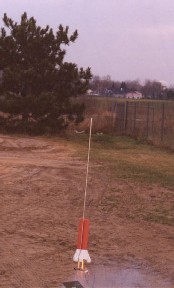
The only damage to date was a separation of the epoxy holding red foam bodies together upon landing on it's noses. This was solved by using more 30 minute epoxy between the red bodies. Ejection gas from one of the engines blew through and out the side of one of the red bodies. The blow-through was due to not enough glue at the head of the motor cavity allowing ejection gas to get into the foam body. This was also repaired with extra epoxy. The second flight had no further damage. The take-off photo is of the second flight on three B4-4s.

Sponsored Ads


 |
 |