Scratch Federated Transport and Delivery Original Design / Scratch Built
Scratch - Federated Transport and Delivery {Scratch}
Contributed by Geoffrey Kerbel
| Manufacturer: | Scratch |
Federated Transport and Delivery
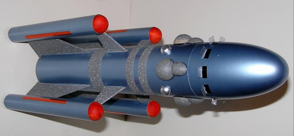
Click on ANY picture to enlarge!
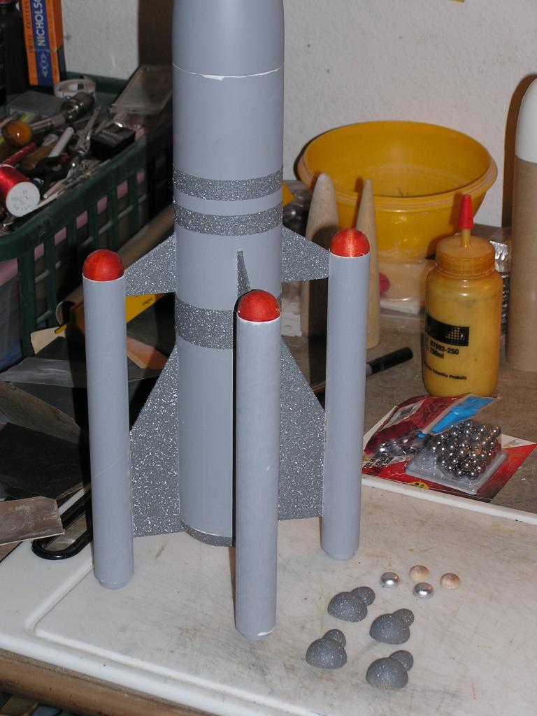
This rocket was conceived from a picture that was part of a contest that Nick of EMRR came up with in mid 2006. There was a group of six pictures he found on the net and decided to give us a chance to design, build and fly one of the rockets in the pictures. Since I have had little to no trouble with clustering, up to this point, I decided to take a shot at the rocket you see in this write up. However, keep in mind, if you are going to attempt to build one of these yourself, that lighting four engines together is a risky endeavor by itself and having them spaced so far apart is even riskier.
The basic rocket is very easy to construct, with the most time and labor being the finishing. This is a two-tone paint job with multiple masking and remasking required to achieve it.
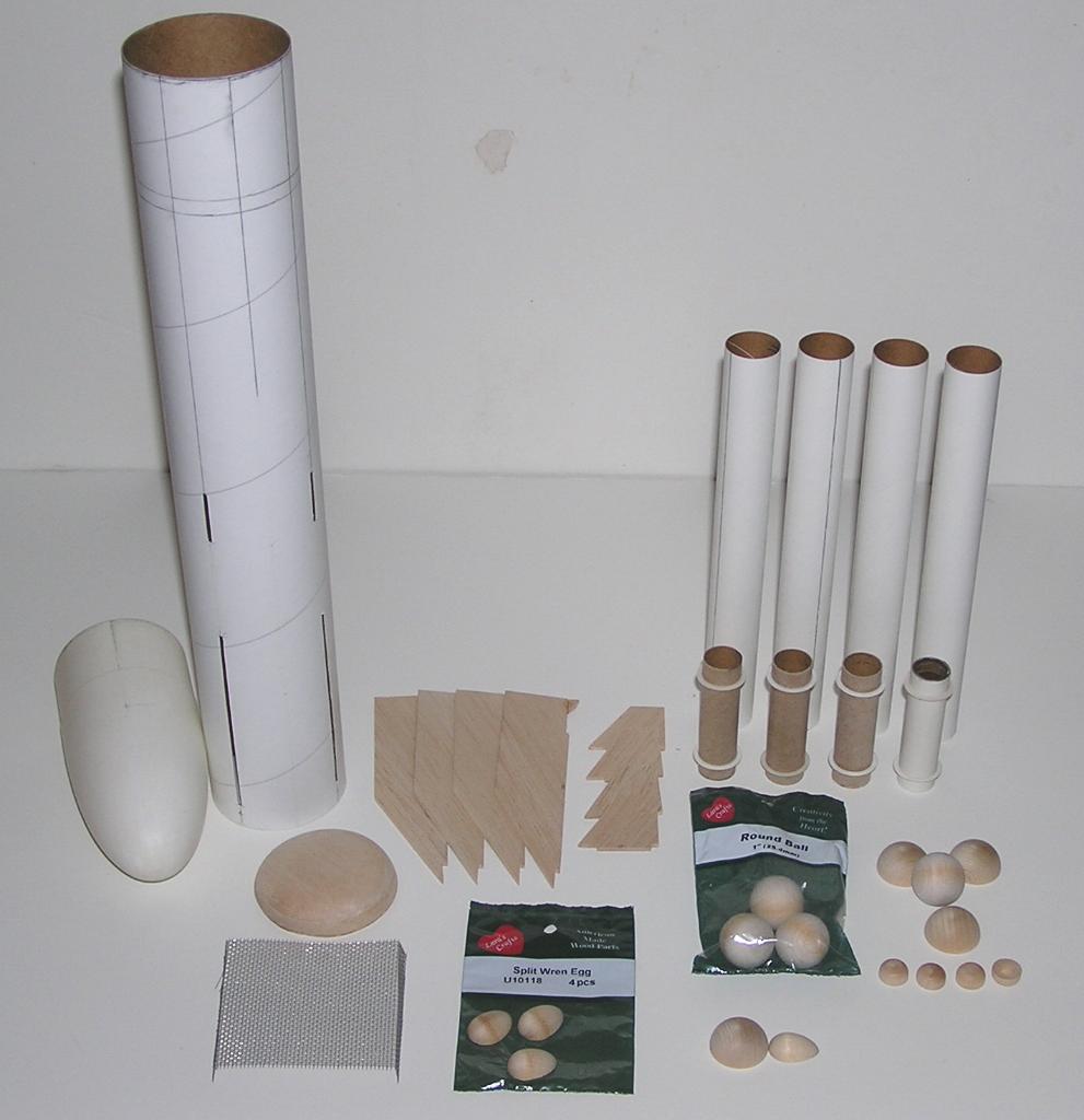 The parts list
is as follows:
The parts list
is as follows:
- One 12" long BT-80 main body tube
- One standard Estes short BT-80 PNC
- Four BT-50 tubes 8.5" long for the motor/outer fin tubes
- Four BT-20 tubes 2.75" long for the motor mounts
- Eight CR2050 rings
- Four 18mm engine blocks
- Two pieces of 3/8" balsa 3.25" square for the main body tube lower end cap
- Two 36" lengths of #150 Kevlar
- Two 10" lengths of #150 Kevlar
- Two 36" lengths of 1/8" elastic
- Two 18" chutes of your choice
- Four 1" wooden balls
- Four 1" wood half spheres
- Four small wood half-robin eggs
- Four small eyehooks
- Four ¼" wood half spheres
- Small piece of metal screen patching material
- 3/32" balsa for the fins
- 8 to 10 oz. of fishing weights
- Rattle can of gray/white auto trunk splatter paint
- Rattle can of Dupli-color DS GM 302 light blue
- Three fin guides from VPC; one for four fins, one for eight fins and one for ten fins
- You will also need wood glue (Titebond II), thin CA, and some 5 min. epoxy and four different sizes of masking tape plus a lot of BB’s or clay.
All of the small trim and detail pieces can be found at your local crafts store. I picked up mine at the local Michaels. I used solid wood pieces because the Rocksim that was made for this rocket showed that a very large amount of nose weight was going to be needed for stability. By making the trim pieces heavy to begin with meant that a little less nose weight would be need later on. At least that was the theory.
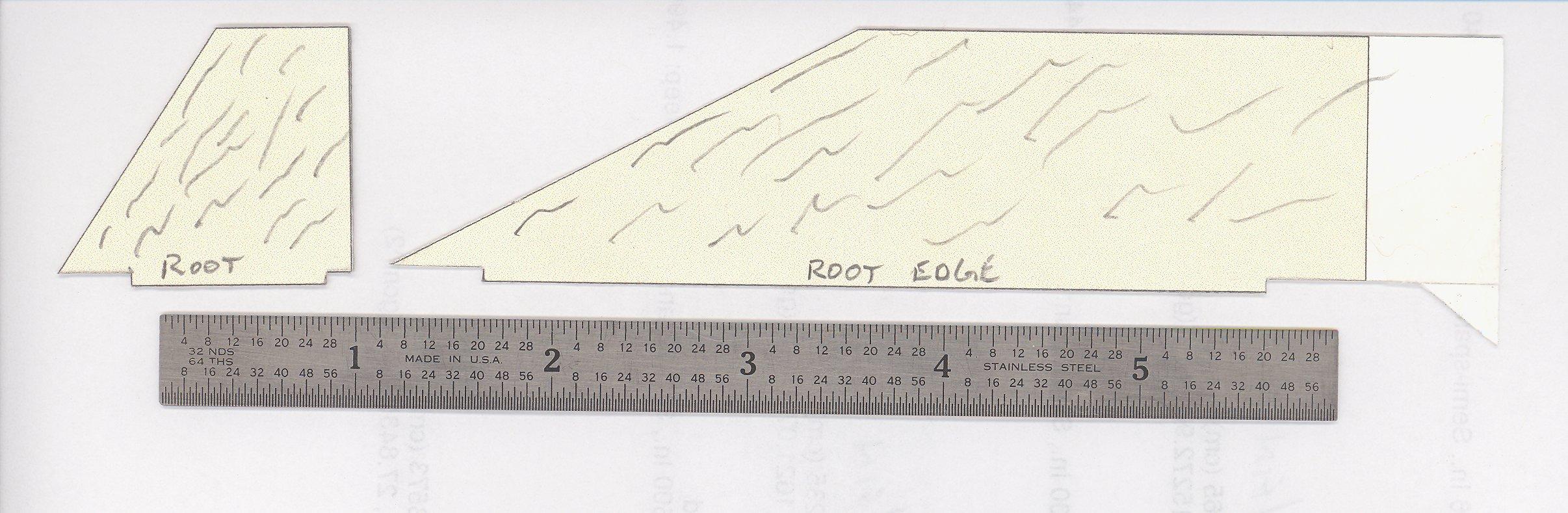
Construction is best done on this one in groups of similar parts. First thing is to cut out the fins. Using the fin guide carefully cut out the four forward and four rear fins making sure the grain direction is followed. Try to use the heaviest, dense balsa you can find because these fins are going to carry the thrust load from the engines for flight. Because of the amount of weight in the nose and the fact that the engines are away from the centerline of the main body tube, the motors are going to place more load on the fins than is usually found on most rockets. Make these as strong as you can without excessive weight! The fins have a very short tab on them for TTW mounting but they do not go into the body tube far. There is nothing for them to bottom out on. You will see what to do as construction continues. After all are cut and sanded to even out all the edges, round the leading edge of each. Put the first thin coating of wood glue on the root edge and the outside edge for the double glue joint to be used later and place all the fins aside to dry.
 Next
subassemblies are the motor mounts. These are standard Estes type mounts
without the engine hooks. The motors will be friction fit to eliminate the
excess weight of the hooks. Take one of the long pieces of Kevlar and slide it
through one of the rings and then slide the ring onto the motor tube. Tie the
Kevlar around the motor tube and pull it up to the bottom of the ring. This is
the upper motor ring and is glued to the motor tube so that the ring is flush
with the end of the tube. Use a generous glue fillet to hold the ring in place
and the Kevlar at the same time. Wood glue was used for this but the thin CA
may be better for a little less weight. Do not get glue on the outside edge of
any of these rings. This is the standard Quest style of shock cord mounting.
Repeat this with the other long and the two shorter Kevlar cords on the other
motor tubes. The lower ring is glued onto the motor tube 3/8" up from the
bottom on each of the motor tubes. Put some glue into the upper end of the
motor tube and using an old motor as a guide push the engine block in
from the bottom so that about ¼" of the motor is
sticking out of the bottom of the mount. Pull the motor out as soon as the
engine block is in position. Set these assemblies aside to dry.
Next
subassemblies are the motor mounts. These are standard Estes type mounts
without the engine hooks. The motors will be friction fit to eliminate the
excess weight of the hooks. Take one of the long pieces of Kevlar and slide it
through one of the rings and then slide the ring onto the motor tube. Tie the
Kevlar around the motor tube and pull it up to the bottom of the ring. This is
the upper motor ring and is glued to the motor tube so that the ring is flush
with the end of the tube. Use a generous glue fillet to hold the ring in place
and the Kevlar at the same time. Wood glue was used for this but the thin CA
may be better for a little less weight. Do not get glue on the outside edge of
any of these rings. This is the standard Quest style of shock cord mounting.
Repeat this with the other long and the two shorter Kevlar cords on the other
motor tubes. The lower ring is glued onto the motor tube 3/8" up from the
bottom on each of the motor tubes. Put some glue into the upper end of the
motor tube and using an old motor as a guide push the engine block in
from the bottom so that about ¼" of the motor is
sticking out of the bottom of the mount. Pull the motor out as soon as the
engine block is in position. Set these assemblies aside to dry.
Take the four wood balls and drill a small hole in the center of each just large enough and deep enough to screw the screw eyes into. Thread each screw eye in and then remove. Use some CA or epoxy in the hole and put the screw eye back in. These will be the "nose cones".
Take the half robin eggs and sand a flat into the large end. Do the same with the half spheres that is about the same size as the flat on the half eggs. Using epoxy, joint the two together. Do this on some wax paper so the pieces don’t stick to whatever they are on. Try to build a nice fillet between the two so that they appear to be one piece when finished. Do this on all four and set aside to dry.
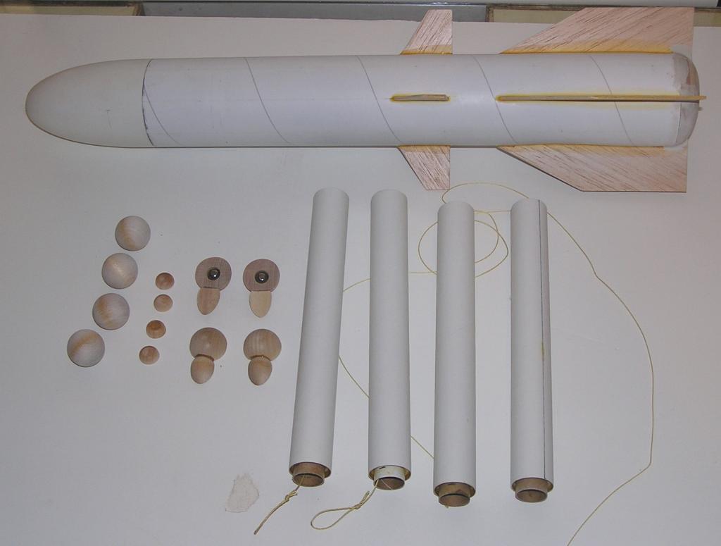
Next up is the bottom plug for the BT-80 main body tube. Take the two 3/8" pieces of balsa and glue them together on top of each other with the grain going "cross pattern". When this has dried, check the alignment of the BT-80 tube on the flat side of this piece. The wood must completely cover the bottom of the tube. If this aligns ok, run a bead of glue around the end of the tube and place it onto the balsa. If not, center it as best you can and use wood filler to close the gaps later. Keep the glue to a minimum on the outside. Keep this upright as the glue dries. Once this has set up, turn the tube over and using a long piece of dowel, run a glue fillet around the inside joint. After this has dried, sand the balsa to form a low dome on the end of the tube. Keep most of the center flat and round the edge over to the diameter of the body tube.
The motor mounts can now be glued into the outer tubes. Take the Kevlar cord and thread it back through the motor mount to get it out of the way. Test fit the motor mounts into the tubes and sand the rings lightly if too tight. The fit should be snug. Either place some wood glue into the tube and then insert the motor mount or insert the mount and then use some thin CA to glue it into place. The motor tube should be about ¼" out from the bottom of the outer tube. Repeat for the other mounts and set them aside to dry.
Use the four-fin guide from VPC on the main body tube to mark the fin positions and using a doorframe or a piece of angle aluminum, extend the lines the full length of the tube. The trailing edge of the fin will be flush with the bottom of the main body. Place the main body upright on a flat surface and align the trailing edge of a fin on the same surface. Slide the fin as close to the tube as possible and mark the ends of the fin tab on the fin line. Measure out the proper amount of tab width on the fin line and use a sharp Xacto knife to make the fin slot. Do this with each of the fins and make sure you mark which fin goes into which slot. The trailing edge of the smaller fin is 7" up from the bottom. Use the same procedure to align the small fin trailing edge with the mark you made and then mark the ends of the fin tabs on the fin line again. Measure and cut the slots for these fins the same as you did for the large fins. Be careful that the two fin slots align straight with each other and straight along the tube. (If you are not good with making these slots, you can use the glue rivet method to hold the fins on) Once the slots are complete and the fins fit into them snuggly, you can start to glue the fins on. Start with a large fin and apply some glue along the edge that will sit flush on the tube. Glue is not needed on the tab at this time. Make sure the fin is all the way into the slot and perpendicular to the body tube. Once this one has set up do the next fin opposite this one. Once it is in place use two small wooden rulers or flat paint sticks with some clothespins to hold the fins parallel to each other. Place the rulers over the bottom edge of the fins and use the pins to hold the rulers in place. Once this is dry repeat the same thing with the other two fins.
The small fins can now be glued in place. Again glue only the tube edge of the fin and use the rulers and pins to hold the small fin in alignment with the large one. Place the rulers over the large fin extending out to the smaller ones. Using the pins, clamp the two rulers over both sides of the fins to hold the smaller one in place. Once dry, repeat one at a time with the other small fins. This should keep all the fins straight with each other and the main body tube.
After all of this has dried, you will want to add a generous amount of glue to the fin tabs from the inside of the main body tube. Using a long dowel again, lay a line of glue along each of the tabs to make a small but strong internal fillet. Again, easy with the amount of glue to keep the weight down but coat the tab well for strength. These fins are going to take the full motor thrust at launch! Let all this dry.
That’s it for the subassemblies, now on to the fun part! The half sphere and robins egg that you glued together, now needs to be shaped to the main body tube. This has to be sanded with a piece of 150 grit paper wrapped around a piece of ½" or so dowel so that the pieces will lay as flat as possible onto the outside of the main body tube. These pieces are of hard wood that will require quite a lot of sanding to shape. If you have any type of electric or air powered sander, you may want to use that. A sanding drum in a Dremel tool is also great to use. Just watch your fingers holding onto the piece and sanding at the same time. The small ¼" half spheres need to be sanded as well. Otherwise just glue these pieces on as is and use some filler to close the gap on the sides. Don’t glue these on yet, however.
 Some of the finishing has to be done at this point which will make
it much easier overall. First up is to place some tape on all the fin outer
edges to keep the paint off. Use a thin line of tape so that the paint will
cover all of the fins. Use your favorite primer (mine is Wallyworld gray) and
prime and sand the main body with the nose cone in place till you have the
smoothness you wish. Do the same to each of the outer tubes with a 1/8"
line of tape running the full length of the tube to protect the glue area from
any paint. There is no particular position on the outer tube to run the tape,
just make the line straight and full length. The glue will stick to the paint
but not hold the pieces together with any kind of strength so the glue area
needs to be unpainted. Measure the tape where the fins will go and cut and
remove the centerpiece so it will be primed. Place all of the other detail
pieces on a flat surface and prime those as well. At this point, all parts
should be primed and sanded smooth to your liking.
Some of the finishing has to be done at this point which will make
it much easier overall. First up is to place some tape on all the fin outer
edges to keep the paint off. Use a thin line of tape so that the paint will
cover all of the fins. Use your favorite primer (mine is Wallyworld gray) and
prime and sand the main body with the nose cone in place till you have the
smoothness you wish. Do the same to each of the outer tubes with a 1/8"
line of tape running the full length of the tube to protect the glue area from
any paint. There is no particular position on the outer tube to run the tape,
just make the line straight and full length. The glue will stick to the paint
but not hold the pieces together with any kind of strength so the glue area
needs to be unpainted. Measure the tape where the fins will go and cut and
remove the centerpiece so it will be primed. Place all of the other detail
pieces on a flat surface and prime those as well. At this point, all parts
should be primed and sanded smooth to your liking.
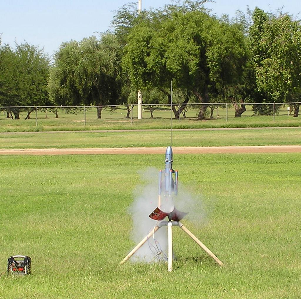
Now for some of the more difficult work! Please refer to the pictures if I get this next step a little unclear. The middle band between the fins is 1" wide and the other two bands are ½" wide. Take some 1" wide tape and wrap it around the main body tube with one edge right at the trailing edge of the small fin. This and the other tape strips are going to be guide strips so they do not have to be pressed down hard onto the tube. Just get them on straight and even all the way around. The first small band starts ¼" in front of the small fin leading edge. I used some ¼" tape to guide the ½" tape. When the first stripe is in position, place a 3/8" band of tape in front of it. Then another ½" piece of tape is wrapped around the main tube in front of the last piece. The bottom of the rocket has the splatter paint on it, as do the fins so now the real work begins! Using whatever tape suits you; you need to mask all the areas that will have the finished color but not the splatter paint. This will take a bit of patience and a very sharp Xacto blade to get right but is the only way to do it. I used low tack painter’s tape and spent almost four hours on this first masking! When this is complete, take the 1" and the ½" tape strips back off. Use a fingernail or blunt object to burnish the tape edges down to minimize the amount of paint that gets under the masking. This will leave the fins, bottom of the rocket and the stripes ready for the trunk paint.
However, to get a proper glue joint and fillet on the outer tube to fin line, you have to glue the outer tubes onto the fins at this point! The forward ends of the tubes are even with the leading edge of the small fins. Remove the lines of tape you used to protect the glue line and glue each tube to the fins making sure they are in line with the main body tube and straight up on the fins. Do one at a time, bracing the rocket so the tubes stay in proper place. When they are all in place and set up, place generous glue fillets on all sides at the joint line. Keep them fairly thin but slightly spread out to get maximum strength at each joint. Let dry.
Once all the outer tubes are in place and dry, mask them completely off for the first paint color. Make especially sure no trunk paint gets into the front or the back of the outer tubes! Don’t worry about not having any primer on the fin fillet, as the trunk paint will stick to the fillet just fine.
The trunk paint is very thick and will go on too heavy if you are not careful! Use very fast strokes and thin amounts of spray to just barely cover the areas you want it on. You want a little of the texture and color but that is all. Complete coverage is also not necessary since the gray primer will blend in with the paint color if it shows through anywhere. Too much will give a blotchy finish and will not blend in well with the finish color. Give this paint about one hour to set up and very carefully remove all of the masking tape. Wherever possible, peel the tape off at an extreme angle so that you are actually cutting an edge into the paint. Go very slowly or you will peel large chunks of the trunk paint off with the tape. Use the Xacto knife to cut the tape away from the paint where necessary. This demasking can get very screwed up very quickly so please take lots of time with it.
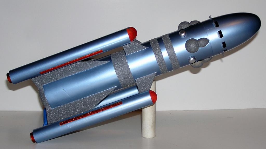
Also remember to use this paint on the half sphere/robins egg pieces. Place the parts on a flat piece of cardboard to spray on but use some folded over masking tape to keep them in place. The trunk paint comes out of the can with much more pressure than normal paint and will blow the parts right off if they are not held down! Give this paint at least one day to completely dry, two would be better.
You’re going to love this next!!!! All the trunk paint now has to be masked off for the finish paint color!!! That’s right, you have to do the whole thing a second time, only this time the masking has to cover all the trunk paint! And the outer tubes are now also in the way! Make sure you use low stick tape or the trunk paint can peel off later when you unmask it. Also make sure the tape sticks somewhat to the paint as you are masking it. The texture of the paint leaves a ruff surface that the tape will have a hard time sticking to in the first place. Once the trunk paint is masked off, touch up any areas that need some primer, sand those areas smooth and apply the finish coat of color. Don’t forget the nose cone. Again remember the cover the front and rear of the outer tubes. The 1" wood balls are a tight fit in the outer tubes as is and any paint will only make it worse. Same with the engines.
Well, we are almost finished! When all the paint is dry, remove all of the masking tape again being very careful with the trunk paint! It can and will peel off if you rip the tape off! Now final assembly can begin.
 First the outer
tubes. Test fit each of the 1" balls at the front of the outer tubes for
smooth sliding in and out. These are the "nose cones" for the rocket.
Sand the inside of the tubes as necessary so that they will pop out when the
ejection charges go off. When you are happy with the fit, feed the Kevlar
through the motor mount and out the front of the outer tube. Two of the outer
tubes will have chutes and the other two will be "dummies". Each pair
must be opposite each other. The two with chutes get the elastic added to the
end of the Kevlar and the elastic tied off to the eyelet on the ball. The other
two just get the Kevlar tied to the eyelet without any elastic. Add the chutes
to the eyelets with the elastic. Tuck everything away into each appropriate
tube so we can now add the detail pieces.
First the outer
tubes. Test fit each of the 1" balls at the front of the outer tubes for
smooth sliding in and out. These are the "nose cones" for the rocket.
Sand the inside of the tubes as necessary so that they will pop out when the
ejection charges go off. When you are happy with the fit, feed the Kevlar
through the motor mount and out the front of the outer tube. Two of the outer
tubes will have chutes and the other two will be "dummies". Each pair
must be opposite each other. The two with chutes get the elastic added to the
end of the Kevlar and the elastic tied off to the eyelet on the ball. The other
two just get the Kevlar tied to the eyelet without any elastic. Add the chutes
to the eyelets with the elastic. Tuck everything away into each appropriate
tube so we can now add the detail pieces.
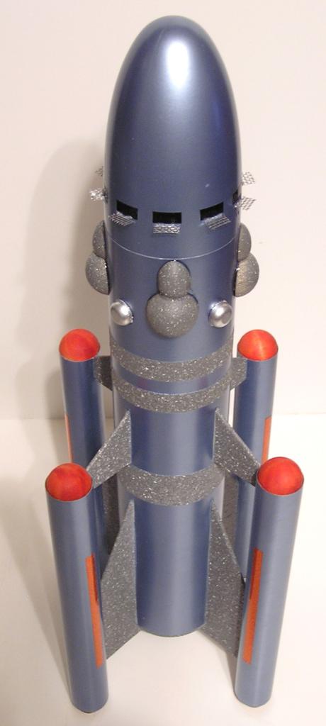
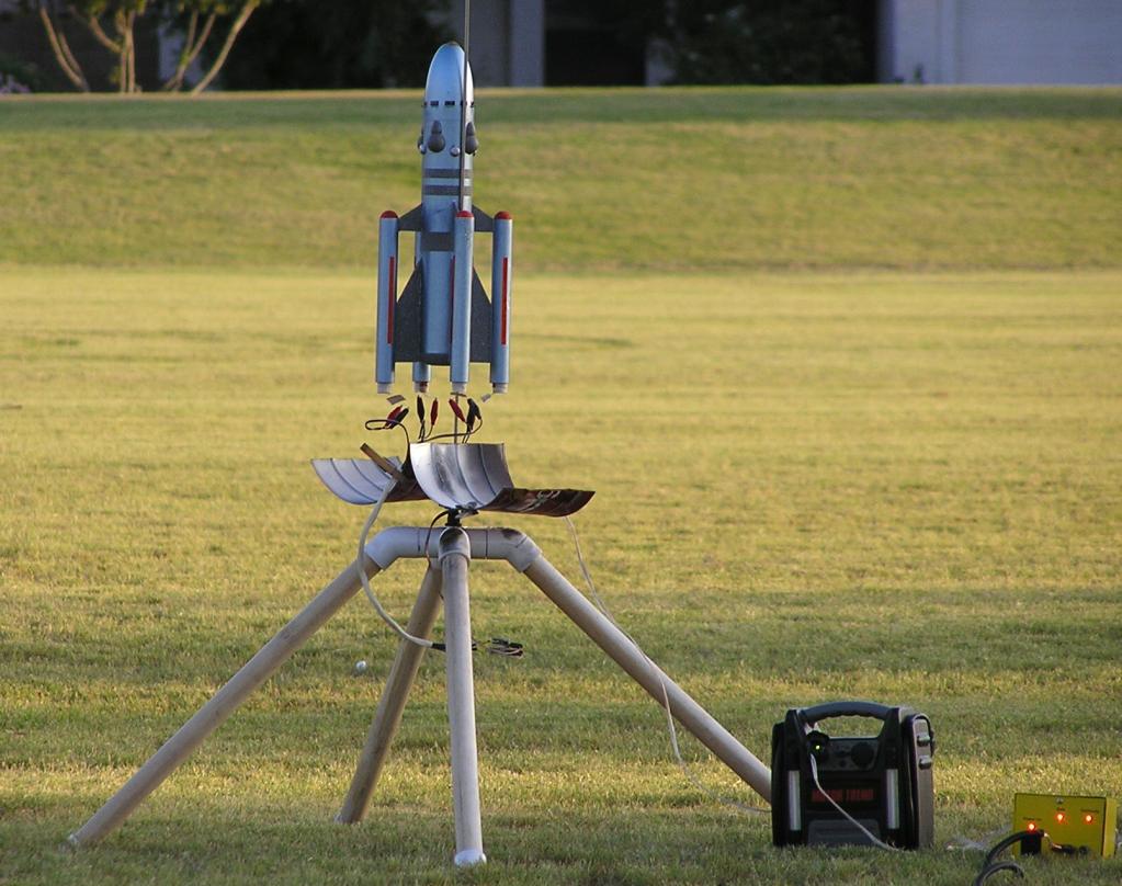
Using an eight fin, fin guide from VPC, line up one of the guidelines with a fin line. Lightly mark all eight points around the body tube close to or at the nose cone line. The half sphere/robins egg piece will line up with the mark between the fins and the small half spheres will be inline with the fins. The egg piece is glued to the body tube with the forward edge of the egg right at the front edge of the body tube. Scrape some of the paint that will be under these pieces off of the body tube to give the glue something to hold on to. Epoxy would be good to use here. If you noticed in the parts picture, the steel ball in the bottom of the egg piece was added early on to get more misc. weight up to the nose. As it turned out, there was so much weight that needed to be added to the nose cone, the time and effort needed to put the balls into the bottom of the piece verses the amount it added, was a waste of time. That is why I didn’t mention about doing it in the build write-up. The small half spheres are glued to the body tube inline with the fins and slightly behind the rear line of the egg pieces. When they are set up, use a brush and some silver paint on them.
The last details are the "ion collectors" on the nose cone but to tell you the truth, it would take another page of instructions on how I did those. Just use a ten fin, fin guide from VPC to make marks on the nose cone about ½" in front of the egg pieces and add some ¼" x 3/8" black decals as on this model and forget the screen pieces. They were a royal pain in the a.. to make and to affix to the rocket. I used an orange Sharpe pen to color the nose cone balls and the ends of the engine tubes. The outer tube orange stripes are made out of strips of prism paper. They are ¼" wide, five inches long and centered on the tubes, end-to-end and side-to-side.
Last but not least the rocket has to be balanced and this is where the whole project almost came to an end! I figured it was going to be tail heavy and the Rocksim showed this to be as well. I didn’t realize just how bad it was going to be. The CP was just about in the middle of the small fin and to be stable, the CG needed to be at least 2.5" in front of that. The CG point came out about at the front edge of the forward trunk paint stripe and I tied a piece of string to the rocket at that point. With four C6-5 engines in their mounts, I tried to lift the rocket at the proper balance point with the string and it went dead tail down fast. Ok, add some nose weight. The sim said eight oz. and that was added to the rocket nose cone way up at the front. Lifting again by the string still came up tail heavy! Ok, more weight! The total came out to ten oz.!! This baby was way nose heavy but apparently in flight balance. Here is the problem; the rocket now weighed 18 oz. That was a lot of weight for the engines to lift and that was if they all lit. Then when the thrust stopped the rocket was sure to start nose down fast with all that weigh up in the front. At that point the ejection charges were sure to go off and if the chutes came out properly, caught air and inflated, the Kevlar was sure to zipper right through the outer tubes!!!!! Not much could be done at this point as it was getting close to the contest deadline and I still had to fly this bird. Oh well, no guts, no glory. Or is that gory!!
8-16-2006
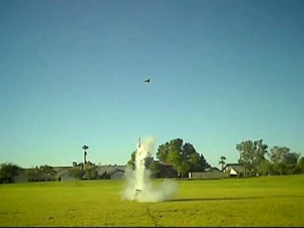
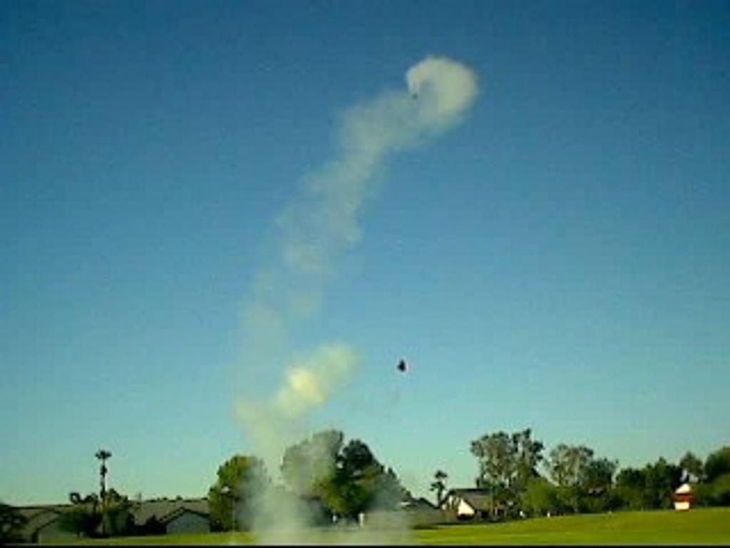
The first flight was on a beautiful calm day. I wish I could say the same for me! All the tubes were loaded with three sheets of Estes wadding and about an inch of "dog barf". The chutes were carefully packed and the ball nose cones were placed about half their diameter into the tube ends. All the tubes were loaded with Estes C5-3 engines via friction fit, thinking the extra launch boost spike would help get some height out of this fat bird. With a friend taking the video and one hand on the camera and the other on the launch controller, I called it down and firmly pushed the launch button. With the camera in my face I didn’t see it get off the rod but instantly realized just from the sound that something was not right. Looking up I caught a quick glance of it doing its third loop-de-loop as it impacted the soft grass. I told my friend to wait for it and soon enough we were rewarded with three quick pops as the wooden balls, chutes and barf all came flying out of the end tubes. Yes, just three! In all the times I have fired off clusters, I have never had a problem till now! Figures, doesn’t it?
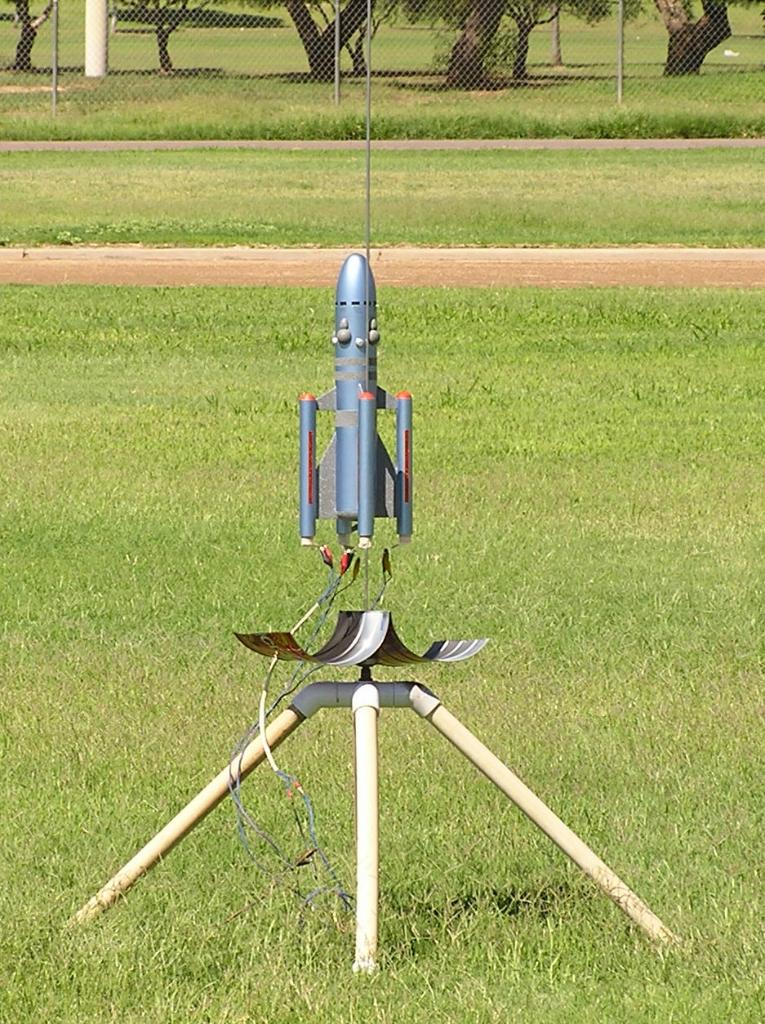
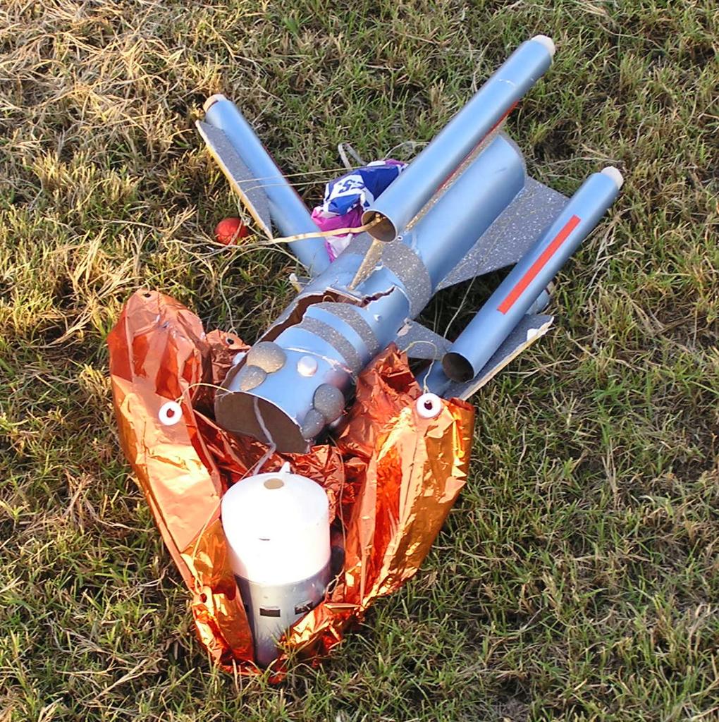
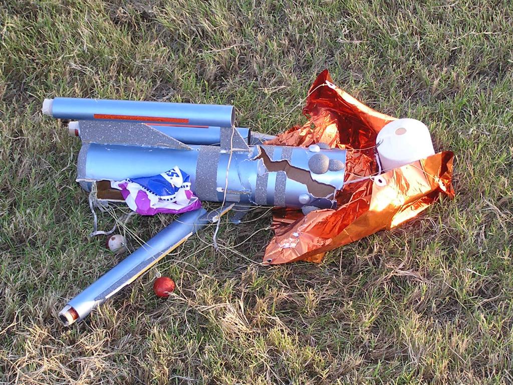
Picking up the pieces, it was obvious that one of the engines didn’t light. My friend played back the video and we could see where it started up ok with the three engines going but quickly nosed over to the unlit side and just as quickly went unstable. I checked the igniters and three of them were burned clean though but the fourth was burned but not completely. The one still shot I got, was beautiful as well. One engine was burning and nothing else was going yet! Luckily, the one was not enough to get it moving until the two others lit up as well. Great time to have a weak igniter!!! Anyway, the rocket was in no shape to fly again that day but the damage turned out to be not too bad. One outer tube broke clean off at the fin line and two other fin sets were showing joint cracks. Some of the nose cone screens were bent and one was missing. Both chutes were charred which was a small surprise. There were some areas of minor tube crease but not much else. The repairs were made rather quickly once I got it home but it ain’t so pretty anymore!
If nothing else, on the next flight I plan to fit the nose cone onto the main body tube very loose so that when the rocket starts nose down and the chutes pop out the side tubes, I am hoping the nose cone will fall out pulling its own chute with it and not allow the side tubes to possibly zipper. That is if I can get them all to light. We will see!
8-23-06:
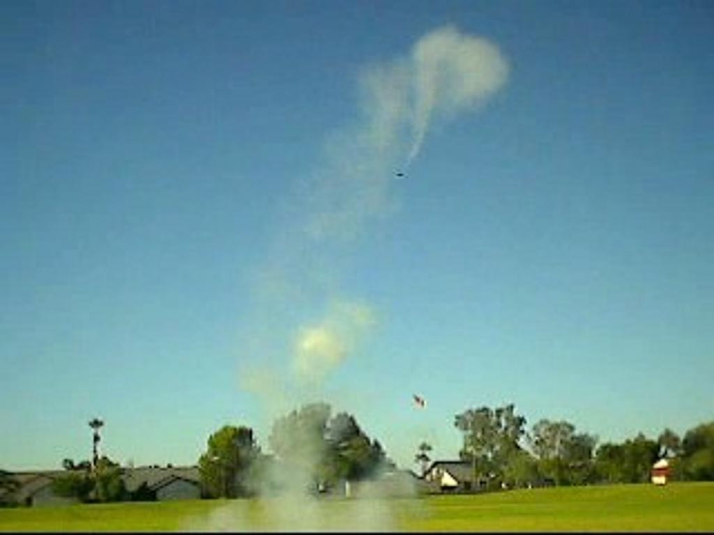
The second flight was on two Estes C6-5 and two Estes C6-0 engines.
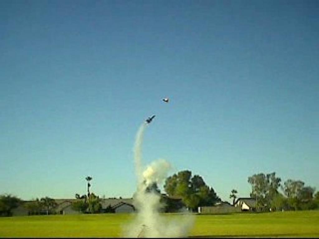
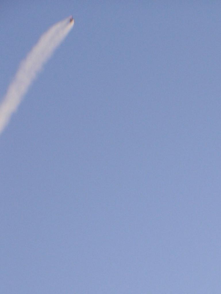
Time for another try! Made up a new clip whip with 12" leads and enough ends to light four engines. Packed it up the same as the first try but the nose cone is now on very loosely and it has its own 24" chute. Hopefully, when the nose is down and the ejection charges go off, the whole thing will slide out and land separately by itself. I double-checked everything, the sky was clear and the button was pushed. I had my small a/v camera with me and it was running as the motors came to life. A split second after they all lit, there was a good size pow with a lot more smoke than four engines lifting the rocket up should have had! At the same time it appeared that something was going up a lot faster than the rocket and I realized that one of the motors had just CATO’ed and sent one of the chutes into its own orbit. Unbelievable!!! The rocket was now under power of three engines again and it did actually manage to get some height fairly straight up when it again went unstable. This time it started a corkscrew got about halfway through that and then went horizontal. I hoped it was a short burn because now it was headed for the front of some houses across the street from that end of the park! Sure enough it went to coast which of course meant mostly down and landed in the park about two hundred feet away with a loud thud. Next was the pop, pop, pop of the ejection charges. When I got to it, I could see two engine tubes broken clean off, a big tangle of the chute lines and the other two nose balls with their lines and some damage to the nose. After collecting it all up and arriving home, the damage didn’t look too extensive and repairs again were made. The bad motor had managed to spit both the ejection charge out and the nozzle at the same time. About two hours later it was in good enough shape to fly again but it took about two more hours of massive grunting and pulling to get the nose cone out of the main body tube! It had been pushed in a quarter of an inch and totally jammed at that point. The tube did not split, to my amazement but the upper part was now larger than the shoulder diameter. Well that would only make it a little looser so that the nose should now have no trouble falling off on the next flight!

8-28-06
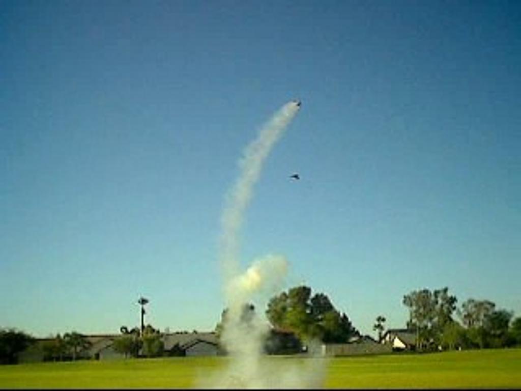
The third flight was with four Estes C6-3 engines.
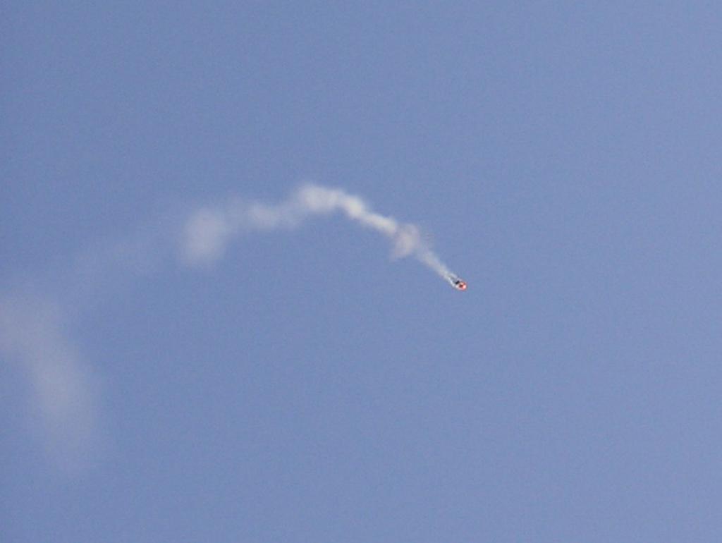
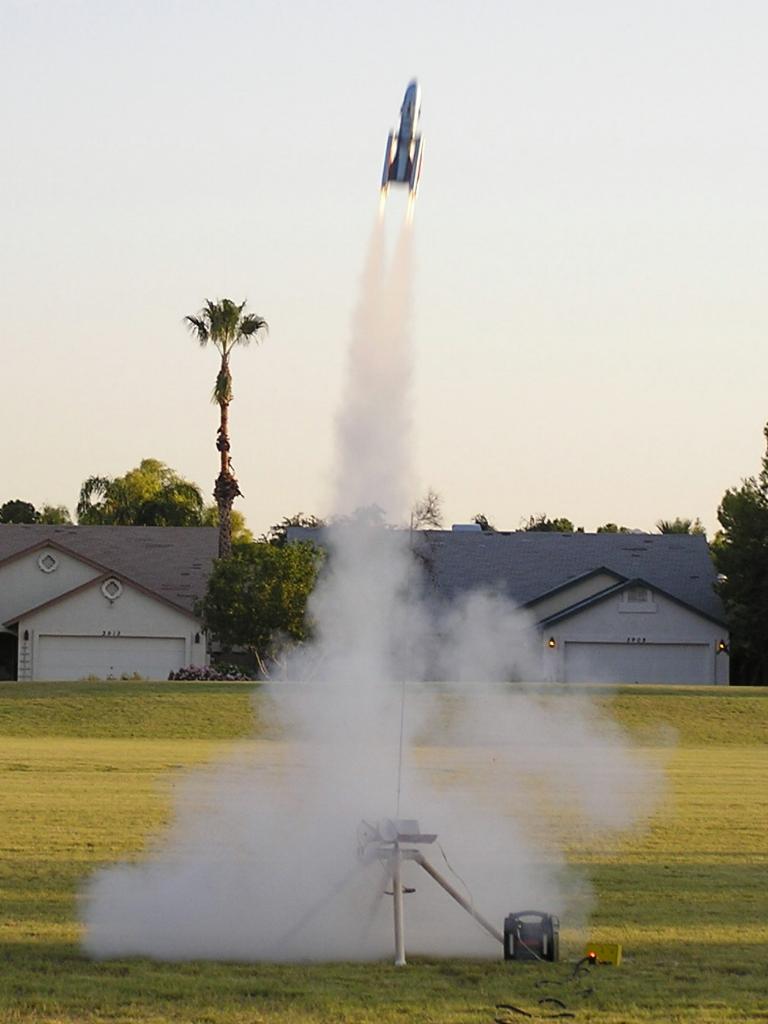
Well, is the third time going to be the charm!! Man I hope so. I don’t think this thing can take any more of those "landings". This time I had the still camera with me and was hoping to get multiple shots as it went up and came down. The camera was set for sequential shots, everything was checked again and I let it rip. WOW, all four came to life and up it went!! Straight and true!!! I just kept the camera going and aimed it as best I could, as I wanted to see this one go. Up and up to about 400’+ just like the sim. said it would and over it went. A split second later I heard the ejection charges go off and again it looked like one of the chutes was spit out and separated! Then the rocket just kept heading down and the second chute was nowhere to be seen. There was no nose separation either! I knew this one was going to be fatal and another loud thud came as it hit. Man, I was bummed! As I got to it, it was obvious that it was finished. Two engine tubes were again broken off and the nose cone was about two inches into the soft dirt with the chute under it. The chute came out but managed to get impaled on the nose cone and that was that. The main body, this time, had exploded open in the front and the back and there was no way I was going to fix that. At least it is nicely preserved in the pictures I have of it.
Overall this was a very challenging project with less than stellar results. I was so fixated on the contest outline of rules and the actual picture that I really didn’t think this one through as thoroughly as I should have. Now it is obvious that I should have at least added a central engine or two to add to the takeoff thrust and to get the main body tube nose cone off of the rocket at apogee to get rid of the excess nose weight to reduce the chance of any zippers. I now have a few other ideas and based on the response of the people that saw the finished rocket, I might just make another that should work much better.
Thanks for your time for one of my long-winded write ups and Nick, let's not do this again for a long time, ok?
 |
 |