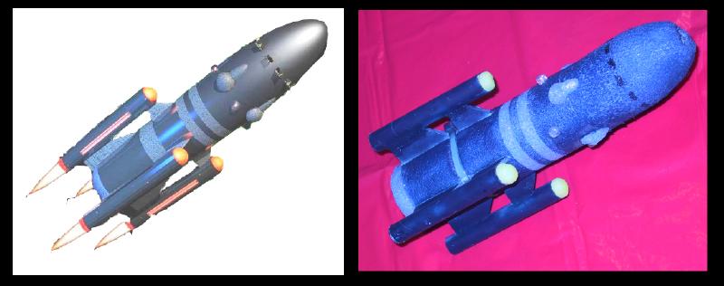
Scratch Cluster Boink Original Design / Scratch Built
Scratch - Cluster Boink {Scratch}
Contributed by Scott Turnbull
| Manufacturer: | Scratch |
Building the CLUSTER BOINK
Overview:
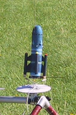
This entry describes the construction of The Cluster Boink, a foam rocket with clustered engines. It features four engine pods mounted at the tips of support struts that extend outfrom the main airframe. The off center engines are required to light as opposing pairs to provide symmetrical thrust. The rocket utilizes passive recovery that relies upon its light weight, large surface area, and foam construction to "boink" when it lands.
Bill of Materials:
- blue foam swim noodle with a hole running lengthwise through the noodle (for main airframe)
- foam board (for engine pod struts)
- four short 18mm motor tubes for engine pods
- one long 18mm motor tube (to stiffen foam core)
- two straws (for internal launch lug sleeve)
- one used 24mm motor casing
- one used 18mm motor casing
Construction of Airframe:
The main airframe is fashioned from a single piece of foam swim noodle. A miter box and fine-toothed saw were used to cut the appropriate length section from the long foam noodle.
Using scissors, clip the squared off edge at one end of the airframe. Now use the scissors to clip off the two resulting edges. Then use the scissors to clip off the resulting four edges. Continue the process of clipping edges until the bullet shaped nose is fashioned at one end of the foam airframe. Rough filing and sanding can be done to produce the final shape.
Using similar techniques, gently round off the lower end of the airframe to match the reference photo.
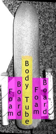
Use a heat gun to slightly melt and glaze the fuzzy foam surface that results from sanding the foam. Force a long length of 18mm motor mount into the central hole at the bottom of the airframe to make the airframe more rigid. This will also serve as a hard mount point for the through the foam engine pod support struts.
 |
Construction of Engine Pods and Support Struts:
Cut rectangles of foam board that are approximately 80% of the engine pod tube lengths, and are wide enough to reach from the edge of the central airframe tube out to the appropriate offset for the engine pods. Use a razor knife to slice four equally spaced slots in the side of the foam airframe. The slots should start an inch above the bottom of the foam airframe, and continue just high enough to provide a press fit for the engine pod support struts. Cut all the way down to the central air frame body tube.
Use Gorilla Glue smeared on the edges and surface of the foam board rectangles to glue the engine pod struts into the airframe slots and to the central body tube. When the glue has dried, use a razor knife to cut the angle for the leading edge of each pod support strut. Also cut out the gap between the forward and rear portions of each engine pod support strut.
Mount a thrust ring inside each engine pod to simplify engine prep. No retention clips were used for this particular construction project, though they could be added if desired. Use Gorilla Glue to attach an engine pod to the outer edge of each engine pod support strut (the foam board). Pay attention that the thrust rings are all at the rear of the mounted engine pods.
Thread a cable zip tie through the gaps cut in the four pod support struts, and cinch it tight enough to just begin to compress the foam airframe. This cable tie provides a mechanical interlock that holds the engine pod support struts tightly against the body tube inside the foam airframe. Now the foam board cannot be pulled free of the central body tube.
Creating an Internal Launch Lug and Plugging Other Holes:
Using a length of brass tubing, force the tube up through the foam airframe parallel to the central body tube. This will remove a foam core sample and leave behind a channel running up the length of the air frame. Force straws into the tunnel in the foam to serve as a smooth tunnel wall for sliding up a launch rod.
A similar core sampling technique can be used with a copper pipe and a scrap piece of foam to create a blue foam plug. This plug is used to fill the central body tube hole at the bottom of the airframe. Note that an optional thrust ring could be added to the central body tube allow a central motor to be mounted in the airframe.
A yellow foam swim noodle donated core samples that were trimmed and heat glazed to form the engine pod forward tips. Appropriate nose cones or paper wadding can also be used as options for plugging the forward ends of the engine pods.
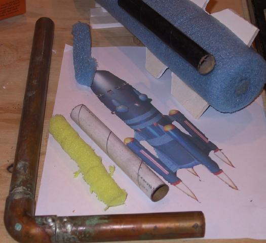
The hole in the nose of the airframe is plugged by forcing in a used 24mm engine casing with the nozzle pointing towards the rear of the airframe. A used 18mm engine casing can then be press fit, nozzle up, into the 24mm casing. This forms a crude payload section within the nose of the airframe. This payload section can be used for the addition of any required nose weight.
Finishing the Engine Pods and Airframe:
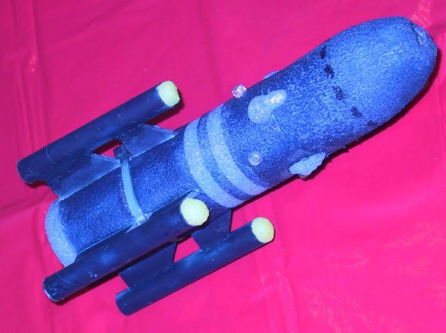
Use masking tape to mask off the areas of the foam airframe that should remain the original blue foam color. The reference photo shows a single ring at the bottom, and two rings above the engine pod support struts. Use caution when selecting a dark blue paint to ensure that it will not dissolve the foam airframe or foamboard struts. I used acrylic paint in an airbrush to apply the dark blue overcoat. When that is dry, peel off the masking tape, and wipe the paint off the glossy cable zip tie to reveal the light blue rings.
Additional Doodads and Details:
The design reference photo shows additional details attached to the forward section of the bullet shaped airframe. Additional core samples of blue foam noodle were shaped and glued onto the foam airframe to approximate those doodads. Clear plastic beads were hot glued to the airframe to represent navigation beacons. A marker pen was used to add additional details for hatches and seams.
 |
Flight Preparation:
Flight preparation is very simple. The main airframe and engine pods are quite light, and boink recovery is acceptably gentle.
The question to answer is what to do with the spent engine casings.
The builder has the choice of gluing in engine pod forward closures. If that is done, the engines will eject. This may require the addition of short streamers to the engines to satisfy some Range Safety Officers.
Another alternative would be to use a short length of recovery harness to attach a nosecone to each engine pod. With that method, the nosecones will pop off, and the boink recovery can be executed with or without attached streamers.
This particular design has been tested with ejecting motors, and with retained motors. It has flow with foam pod caps, no pod caps, and wadded crepe paper pod cap streamers. At ejection, the wadded streamers pop out of the engine pods and the boink recovery is executed with a minor extra flourish.
Flight Results:
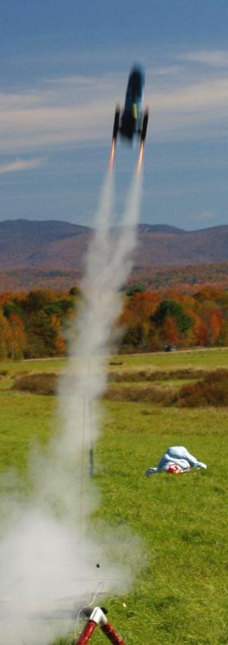
 The first flight was done with two A8-3 engines, mounted in opposing engine pods. Yellow foam plugs were initially glued into all four engine pods. At ignition, both engines ignited, and the rocket boosted cleanly to 20 or 30 feet, then the Cluster Boink did a couple of quick flips. It is possible that one engine stopped thrusting and the other engine's last gasp produced asymmetrical thrust. The ejection charges blew out the engines, and the glued foam plugs. It seems that the glue is stronger than the foam and that the strength of the foam wasn't up to containing the ejection pressure. A skim coat of foam plug residue remained glued to the inside of the two engine pods. The boink recovery executed perfectly with no rocket damage.
The next flight was done on two B6-4 engines, mounted in the same opposing engine pods. No engine pod plugs were installed for this flight. A small amount of gravel was added to the payload bay for noseweight. On this flight only one engine lit, and the rocket looped a couple of times before falling gently to the ground, followed shortly thereafter by the ejection charges. This flight is a good example of the (non)flight characteristics of this rocket with unbalanced thrust.
 On another day a repeat flight with two A8-3’s was done without the extra nose weight. For this flight, orange crepe paper streamers were wedged in and held by the motors. The streamers were wadded up to plug the upper engine pod tubes. Both engines lit, and another arcing flight of 20 or 30 feet resulted. The engines ejected, the streamers streamed, and the boink boinked.
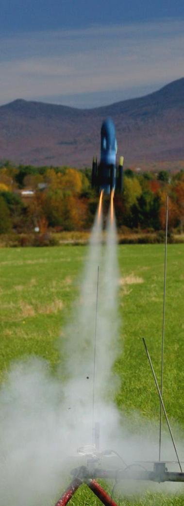 A fourth flight on two B6-4 engines was done using the crepe paper streamers and no added nose weight. Both engines lit, but the missing nose weight resulted in a marginally stable flight. The rocket went up about 30 feet, and then executed some loops before ejecting, streaming, and boinking as designed.
Determined to prove the Cluster Boink could get some altitude, a third launch event took place. For this flight BB shot was added to the payload section. Two B6-4 engines were installed. The two loaded engine pods were left uncapped and without streamers. At ignition, both engines lit right up, and the boost was very stable to a considerable altitude. The Cluster Boink fell to the hard gravel running track about 30 feet away, bounced high in the air, and is ready to fly again without repairs.


 |
 |