| Manufacturer: | LOC/Precision  |
 Contributed -
by Gary Sinclair - 07/10/01)
Contributed -
by Gary Sinclair - 07/10/01) Brief:
Fiberglassed airframe and fins with additional tip-tip lay-up on mounted fins.
Shockcord replaced with 3mm tubular Kevlar® mounted directly to motor mount
through forward centering ring.
Modifications:
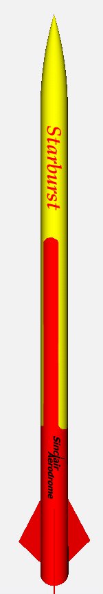
As my first cluster rocket I decided upon a LOC Starburst which has two 24mm
motors mounted within a 2.6" OD airframe. I liked the look of this kit as
it had a payload bay (great for holding trackers etc.. and for attachment of
recovery harnesses) and sported a nice delta fin shape. LOC kits are also
perfect for lay-ups as they are thin-walled, strong and light. With this in
mind I used one layer of 4oz fiberglass with West Systems epoxy to reinforce
the airframe and fins (fins were first bevelled using my Dremel to a nice sharp
edge). The lay-up was then vacuum bagged using my food saver. Centering rings
and motor mounts were mounted in the airframe prior to mounting the fins. Note
the fin tabs only partially extend into the airframe and should mount onto the
forward centering ring. Once the fins had cured I further reinforced the fin to
airframe bond with a tip to tip lay-up of 4oz fiberglass. To reduce the amount
of resin in the fin-fin lay-up!
I put my rocket on my ROBARTS rocket stand so the fins were cradled by the supports. I then proceeded to cover the lay-up first with a resin-release film followed by cotton batting to soak up the excess resin which would seep through the film. Note for this to work you have to apply weight onto the top of the cotton so it presses down onto the fins and airframe. Take care you don't break your nice new fin assembly in the process. John Coker has a nice jig you can build to support your rockets as the right angle to reduce this kind of damage. The rest of the rocket went together stock.
Components:
- 1 - 34" x 2.6" body tube
- 1 - 9" x 2.6" payload section
- 1 - 4" coupler tube
- 1 - 2.6" OD Ogive nosecone (3 to 1)
- 2 - 12" x 24mm motor mount tubes
- 2 - Birch plywood centering rings
- 1 - Forward coupler bulkhead with hardware assembly
- 3 - Birch plywood fins (triangle shaped) with small tabs for partial 'through the wall' mounting.
- 1 - Elastic shockcord
- 1 - LOC 12" nylon parachute - pink
 Construction:
LOC kits tend to be brief on the instructions but are detailed where necessary (e.g. motor mount assembly of clusters). The packaging is your standard 'bag with a front card' and all parts were accounted for and unbroken. The kit was easy to build and my modifications where in keeping with the general steps taken when building this kit stock. After all construction was completed the rocket was rock solid and ready for finishing.
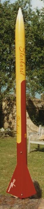
To finish this kit I applied a layer of SuperFil to the fin can area to cover the tip-tip lay-up and create small fillets. Once the SuperFil had dried sufficiently I applied several coats of UV SmoothPrime on the rest of the airframe and over the SuperFil (un-sanded at this point). After the SmoothPrime had dried for a couple of days I took my JCB Palm sander and went to work with a medium grit sandpaper at first and then switching to a wet/dry fine grit. The layers of SmoothPrime and SuperFil sand easily so beware when using anything rough on them. After sanding the airframe and fins to a nice smooth finish I had to apply a spraying of grey filler primer to show up any inconsistencies. A bit of SuperFil was used to fill any areas missed and then sanded smooth prior to more grey filler primer. Eventually I was ready to paint. For my color scheme I decided to replicate the look of PML's similar looking Quasar. This is a yellow and red combination with a bit of white at the nosecone tip.
Flight:
I wanted the biggest 24mm motors I could find to fly in this rocket so I chose
two G55-10s which together would give me about 240 newtons of force. In a 27oz
rocket 240 newtons would boost it over 3000 feet at 400mph. Prior to the launch
I used a couple of 24mm thrust rings I purchased from Apogee to keep the single
use motors from thrusting all the way into the airframe. The thrust rings were
epoxied into the airframe at the deepest point the long G55 motors would
extend. Motor retention consisted of two threaded nuts drilled into the aft
centering ring. Into these bolts and washers were used to hold onto the motor
casing.
Launch photos are by Bob
Arnott
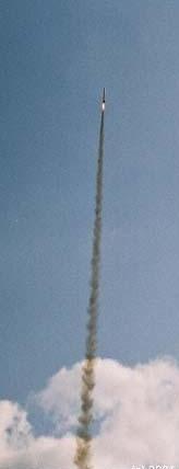
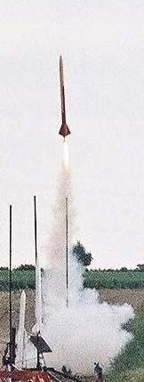
The flight was fast and high. The photos showed a wobble which seemed to indicate that the motors did not ignite at the same time. The result was that the thrust curves of the two motors were not in sync. Hence the push in one direction and then the other. After the first 1/2 second the thrust curves had converged and the rocket travelled straight and fast to 3400 feet (ROCKSIM prediction).
Recovery was about 1 mile down range in the middle of an adjacent field of fully grown crops. Fortunately I had a Marshal tracker installed so it was easy to find (after some leg work). The rocket was recovered with no damage ready to fly again.
Summary:
Pro's: I really like LOC kits and this one has so far worked perfectly. It was
an easy kit to modify and if built stock would be great on smaller engines.
Con's: Well the elastic shock cord is probably OK for this size rocket but I just don't trust them so it should go. Also I prefer to mount my shock cords to the forward centering ring or on the motor mount and not on the airframe wall.
 |
 |
Flights
|
|