| Manufacturer: | Scratch |
Augie - Sport
2-Stage, single-piece, ducted sport flier based on Estes MRN designs Nos. 10 28
Shortly after becoming a BAR a couple of years ago, I accidentally discovered JimZ Rocket Plans site on the web and was overcome by nostalgia. I quickly downloaded a bunch of old plans, especially the ones from old issues of Estes' Model Rocket News. One that I particularly liked was Estes MRN plan No. 10, Lil' Augie, a two-stage, single-piece, ducted rocket. There's no hidden secret to a ducted design, the idea is to create a two-staged rocket that doesn't carry the extra weight and drag of a booster with large fins. The down-side is that you probably add enough drag with the sustainer motor air ducts to offset the gains of eliminating the booster. Regardless of the aerodynamics, the rocket is fun to fly because of the surprised looks you get from the onlookers when the booster motor snaps clear and the sustainer motor fires. No one ever expects the little rocket to have a second stage, and it really flies quite high, especially when staged C6 to C6. After Lil' Augie I built a second ducted design, the Augie-II, Estes plan No. 28. Same deal, just a modified design -- probably redesigned to avoid the eventual demise of the Lil' Augie, from the sustainer motor singeing the lower airframe. I went on to create my own Augie-III, which was basically an up-scale of Augie-II, staging D12 to D12. Finally, I decided I wanted to update the Augie with a smoother, more aerodynamic design, and I built the Augie-Sport.
In the original Augie designs a smaller-diameter, upper tube and a larger-diameter, lower tube are connected together to form the airframe (i.e. for the Augie-II a BT-20 upper is connected with 4 balsa "fins" to a lower BT-60 airframe). Two 18mm motors are taped (scotch, or transparent tape, not masking tape!) together end-to-end and inserted into the upper BT-20 up to the tape joint. The booster motor is left free-floating, surrounded by the lower, larger airframe tube but held in place by the tape connecting the motors together -- a method now often referred to as C.H.A.D. (CHeap And Dirty) staging. Ducts to supply air for the upper, sustainer motor were created by the gap between the smaller-diameter, upper airframe and the larger-diameter, lower airframe. The air ducts prevent the over-expansion of exhaust gases (the "Krushnic effect") from robbing the sustainer motor's thrust and burning up the lower airframe. This design had the advantage of increased stability as the lower airframe tube acts somewhat as a tube-fin and keeps the center of pressure aft-ward. However it has the disadvantage of adding drag because of the abrupt airframe transition, and also by nature of the fact that drag is directly proportional to area, and in the case of Augie-II the area of the lower airframe is more than 4X that of the smaller upper.
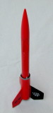
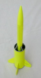
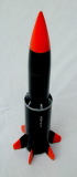
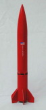
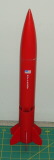
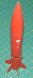
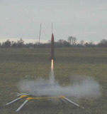
For the new Augie-Sport design I wanted to try to minimize the added drag of the abrupt airframe transition. To accomplish this I used only one airframe diameter for both the lower and upper stage, and built the ducts to draw air into the lower airframe tube to supply the sustainer motor. I wanted to keep some resemblance of the earlier Augie designs, but I was going to significantly change the design of the sustainer's ducting, and given that there isn't much to a rocket that can be carried through from generation to generation, I decided to keep the same fin design as the Augie-II. Finally, I ended up with a roughly 10" long, 6-finned, BT-60 design with 6 open air ducts 4" from the tail of the rocket. The rocket flies beautifully straight using both B6 to B6 and C6 to C6 18mm motors.
Materials:
1. (1) BT-60, 5-1/4"
2. (1) BT-60, 4"
3. (1) BT-20, 3-5/8"
4. (1) PNC-60A
5. (2) BT-20 to BT-60 cardboard centering ring
6. (1) EB-20 engine block
7. (2) LL-3/16", 5-1/8"L
8. (6) Balsa fin (see pattern)
9. (6) Balsa support fin (see pattern)
10. (6) Paper BT-60 to BT-20 transition form (see pattern)
11. (1) 12" chute
12. (1) 24" shock cord
Construction:
Start by constructing the engine mount assembly. Insert engine block into fore end of BT-20 engine tube at a position where the sustainer engine will protrude from the aft-end of the engine tube by 1/2". Glue centering rings 1/8" from the fore end of engine tube and 1-5/8" from aft-end of engine tube.
Next attach the 6 balsa support fins to the engine tube, equally spaced around the engine tube, as shown in the first diagram. Fillet fins for strength.
Glue the 6 BT-60 to BT-20 paper transition sections between each of the 6 support fins. as shown in the second diagram. Coat each transition with 30-minute epoxy to add strength to the paper transition and to fillet each of the support fins.
Attach shock cord to engine mount assembly. I do this by cutting a small slit in the fore centering ring, passing the shock cord through the slit, and tying a knot to hold the shock cord firmly. A small drop of glue on the knot will help to keep the knot from untying and passing back through the slit.
Insert the engine mount assembly into the longer BT-60 airframe section and glue into place.
Slide the shorter BT-60 airframe over the 6 support fins until the two airframe sections are separated by a 3/4" gap, this forms the sustainers air ducts. At this point make sure the airframes line up straight. Glue aft airframe section to support fins and fillet each support inside the aft airframe section.
Attach the 6 balsa fins to the aft airframe. Fins can either be lined up with support fins or offset, whichever look you prefer. One can use the Estes fin alignment guide by taping two spent engine casings together and inserting them into the forward engine tube. Fillet fins (That's a lot of filleting, by-the-way!).
Attach launch lugs at aft end of each airframe section. Fillet lugs.
Attach chute and shock cord to PNC-60 nose cone.
Finish.


Sponsored Ads

 | Intermediate Rocket Kit | Step-by-Step Instructions | Science Education Kits | Great for Teachers, Youth Group Leaders and Birthdays,Blue")


 Rare Made In USA")
 |
 |