| Manufacturer: | Blackhawk R&D |

(Contributed - by Chuck Pierce - 04/01/02)
 Brief:
Blackhawk R&D recently developed a 4-inch diameter prototype of the Russian
SA-5 Gammon. After expressing much interest in the kit, Blackhawk offered me
the opportunity to built and test the prototype kit, which I gladly accepted.
The SA-5 is a Russian surface-to-air (SAM) with twelve fins, four external
booster motors, and a single centerline sustainer motor. The Blackhawk SA-5 is
a 1/8.3 scale model of the Russian missile, having a 4” main airframe with
a 38mm motor tube and four 38mm outboard booster pods with each containing a
29mm motor tube. The Rocket is 54” tall.
Components:
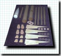
The kit arrived from Blackhawk in two heavy-duty shipping boxes, with the parts
well packed and protected. The components that Blackhawk uses in this kit are
of very high high quality. The airframe and booster tubes are sturdy and the
plastic nosecone is strong. The fins, being 5-ply Baltic Birch, are the highest
quality plywood that I’ve ever used. However, the fins are 1/8”
thick, which seemed a little thin for a kit as heavy as this one is going to
be. I usually prefer 3/16” fins for 4” airframes. The main and
booster airframes arrived pre-slotted for the 12 fins. All plywood pieces were
cut on a CNC machine, resulting in a very nice piece-to-piece repeatability of
dimensions.
- Parts List:
- Plastic Nose Cone, 4:1 ogive,
- 4” x 26.5” Main Airframe,
- 4” x 10” Payload Tube,
- 3.9” x 10” Coupler Tube,
- 38mm x 18” Centerline Motor Tube,
- 38mm x 20” Outboard Booster Airframe (4 each),
- 29mm x 6” Outboard Booster Motor Tube (4 each),
- 1/8” 5-ply Main Airframe Forward Fins TTW (4 each),
- 1/8” 5-ply Main Airframe Aft Fins, TTW (4 each),
- 1/8” 5-ply Outboard Booster Fins, TTW (4 each),
- 1/4” 5-ply 4”/38mm Centering Rings (2 each),
- 1/4" 5-ply 4” Bulkhead,
- 1/8” 5-ply 38mm/29mm Centering Rings (8 each),
- 1/8” ellipse (for booster tube nose cones, 4 each),
- 10’ x 9/16” Tubular Nylon Shock Cord,
- 1/8” x 1/2" Ubolt (2 each),
- 1/2" x 6” rod lug (cut to make a two lugs)
 Construction:
Being a prototype, the SA-5 was kitted without instructions, which isn’t a
problem for an experienced HPR modeler. The assembly sequence that I used to
build the SA-5 worked well, and I’d recommend that the same basic sequence
be followed in future builds of this kit:
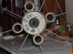
(1) Install the 29mm motor tubes and TTW fins into the outboard booster tubes,
prior to attaching the outboard boosters to the main airframe,
(2) Install the 38mm motor tube and all 8 TTW fins onto the main airframe (with
internal fillets) prior to attaching the outboard booster airframes,
(3) Install the outboard booster assemblies onto the main airframe,
(4) Assemble the payload bay (completely independent of the main airframe and
booster airframe assemblies)
 Though this kit is
designed to be able to be flown with a single centerline motor, the option to
fly a single 38mm/4x29mm motor cluster persuaded me to build an altimeter bay
into the payload bay (for staged deployment) and to wire the main airframe for
dual timers (for staged ignition). Due to the quantity and size of TTW fins,
available volume within the 4” airframes is very limited, making the
incorporation of an altimeter bay a little difficult. The altimeter bay that I
built was 38mm tube which was installed against the inner wall of the 4”
payload bay. This setup allowed me to pack the main parachute along side the
38mm altimeter bay, thus making maximum use of the available internal volume of
the payload bay. To configure the rocket for staged ignition, 3 pairs of 20 AWG
wires were run through the forward 4” CR and terminated at leads tapped
through the aft 4” CR. The three pairs of wires/terminals are planned to
be used for two sets of ignition wires and a break wire for use with a single
or pair of Perfect Flite micro timers.
Though this kit is
designed to be able to be flown with a single centerline motor, the option to
fly a single 38mm/4x29mm motor cluster persuaded me to build an altimeter bay
into the payload bay (for staged deployment) and to wire the main airframe for
dual timers (for staged ignition). Due to the quantity and size of TTW fins,
available volume within the 4” airframes is very limited, making the
incorporation of an altimeter bay a little difficult. The altimeter bay that I
built was 38mm tube which was installed against the inner wall of the 4”
payload bay. This setup allowed me to pack the main parachute along side the
38mm altimeter bay, thus making maximum use of the available internal volume of
the payload bay. To configure the rocket for staged ignition, 3 pairs of 20 AWG
wires were run through the forward 4” CR and terminated at leads tapped
through the aft 4” CR. The three pairs of wires/terminals are planned to
be used for two sets of ignition wires and a break wire for use with a single
or pair of Perfect Flite micro timers.
I spent most evenings working on SA-5 and was able to finish assembling the model in a little over a week. With ample internal and external fillets on the TTW fins and massive booster-to-main-airframe fillets, the kit is very strong and sturdy. I calculated the CP to be 40” behind the tip of the nose cone, but used a CP of 38” for margin when assessing the static stability of the rocket. Due to the size/quantity of fins and the amount of epoxy used to install fins and attach airframe tubes, 12 ounces of nose weight were needed to give the SA-5 one caliber of static stability margin for a reasonable cluster set (I357 with 4x G80 or a single J570). A J570/4xG80 cluster would cause the static stability margin to be reduced to 1/2 caliber, which would still be flyable, though would be deserving of close attention to the launch conditions. Also, nothing precludes the addition of additional nose weight in the future. The 12 ounces of nose weight (10 ounces of #9 lead shot and 2 ounces of epoxy) were poured into the nose cone, and pre-drilled holes through the tip of the nose cone allowed the epoxy to fill the holes, forming epoxy rivets when cured. The epoxy rivets are used to hold the weight in the vertex of the nosecone. To finish the SA-5, a single heavy coat of Zinssler shellac primer was applied to fill any surface irregularities, then well sanded. The SA-5 was then painted to match the standard non-descript Russian paint scheme: winter grey airframe, boosters, and fins with a crimson nose.
Construction Rating: 5 out of 5 (though the beta kit came without instructions, the tight-toleranced TTW components made to it go together quite well.)
Flight/Recovery:
Having only 6 HPR motors remaining in my motor cache after the Aerotech fire,
the available motor choices for the first flight of the SA-5 were very limited.
After debating between an I357, I211, and I284, the I211 was finally selected
for the maiden flight. The SA-5 was configured for flight with an RRC2
altimeter (set for apogee drogue deployment and main deployment at 300’),
a single centerline I211 (medium delay as backup to the altimeter drogue
delay), 58” main parachute, no drogue chute (once separated the fincan
will be unstable and, thus, won’t require a drogue chute), 30’ x
5/8” TK drogue shock cord, 10’ x 5/8” TN main shock cord, and
shear pins were installed at the booster-to-payload (drogue) plane and at the
payload-to-nose-cone (main) plane.
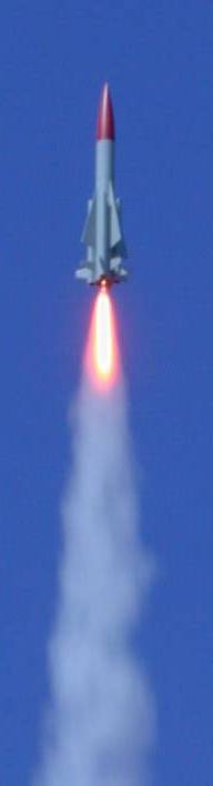 On February 23, 2002,
the SA-5 made her maiden flight in 5-10 knot winds. The trajectory of the SA-5
was almost perfectly vertical to an apogee of 1394 feet (per the altimeter).
Unfortunately, at apogee neither the altimeter-triggered nor motor-backup
ejection charges separated the airframe. Post flight inspection found that that
the altimeter drogue channel pins were broken and that the motor BP had leaked
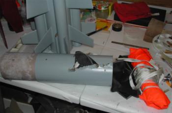
from the ejection well during transport. With no drogue separation, the SA-5
descended ballisticly from apogee to 300 feet, at which point the main chute
was deployed. The recoil from the main chute deployment cut a 5” zipper
into the payload bay and separated the fincan from the payload bay (the joint
that should have been separated at apogee). Luckily, the long drogue shock
cord, with taped coils, did not damage the fincan. Of all the damage that could
have occurred due to this drogue system failure, suffering only a zippered
payload bay was fortunate. The zipper was repaired by filling the gash with
reinforced epoxy, then the exterior of the payload bay was covered with two
wraps of 2-ounce glass. If the payload bay had been glassed during initial
assembly, the SA-5 probably would have escaped this drogue-system failure
undamaged.
On February 23, 2002,
the SA-5 made her maiden flight in 5-10 knot winds. The trajectory of the SA-5
was almost perfectly vertical to an apogee of 1394 feet (per the altimeter).
Unfortunately, at apogee neither the altimeter-triggered nor motor-backup
ejection charges separated the airframe. Post flight inspection found that that
the altimeter drogue channel pins were broken and that the motor BP had leaked
from the ejection well during transport. With no drogue separation, the SA-5
descended ballisticly from apogee to 300 feet, at which point the main chute
was deployed. The recoil from the main chute deployment cut a 5” zipper
into the payload bay and separated the fincan from the payload bay (the joint
that should have been separated at apogee). Luckily, the long drogue shock
cord, with taped coils, did not damage the fincan. Of all the damage that could
have occurred due to this drogue system failure, suffering only a zippered
payload bay was fortunate. The zipper was repaired by filling the gash with
reinforced epoxy, then the exterior of the payload bay was covered with two
wraps of 2-ounce glass. If the payload bay had been glassed during initial
assembly, the SA-5 probably would have escaped this drogue-system failure
undamaged.
On March 23, 2002, the SA-5 was prepped for its second flight, this time with an I285R. The projected altitude was approximately 1500 feet. The skies were perfectly clear and the winds were calm. The boost was again perfectly straight with a nice long Redline flame. Per the altimeter, the rocket tipped over at 1271 feet. On landing however, the rocket hit hard on one of the aft fins, fracturing it inside the airframe. Fortunately though, the damage is reparable though. Based on this, however, I’d highly recommend that 3/16” plywood be used in the production version.
Flight Rating: 4 out of 5 (I believe that 3/16 fins should be used with this kit due to its size)
Overall Observations:
The SA-5 is an outstanding kit! The motor cluster configuration allows the
modeler great flexibility in type and number of motor choices (from single
motor flights to five-motor clusters). In my opinion, this kit is not suitable
for novice HPR modelers, due to the number of fins and tubes involved. For the
more experienced Level 1 or higher flyers, this kit is fun, looks great, and
will be a wonderful attention-getter at launches. A couple of items that
I’d recommend be changed are as follows: (1) I would like to see a longer
shock cord provided with the kit. Longer shock cords are a personal preference
of mine, but I also recognize that many flyers do not share this preference.
Also, since this kit should be targeted toward the more experienced
flyers/modelers, increasing the length of shock cord is an extremely minor
task; so, as such, this suggestion is so minor that it is hardly worth
mentioning. (2) For a kit as intricate and heavy as this one, I’d highly
recommend increasing the fin material from 1/8” ply to 3/16” ply.
Without or without my recommended changes being made, however, the Blackhawk
R&D SA-5 is an outstanding kit, and I highly recommend it!
Overall Rating: 5 out of 5
Manufacturer's Note: Upon release the SA-5 will come with 3/16" fins and that the release date is set to be somewhere during the 1st week of April 2002, we are just waiting on the smaller laser cut parts.
 |
 |