Scratch Sephydra Original Design / Scratch Built
Scratch - Sephydra {Scratch}
Contributed by Geof Givens
| Manufacturer: | Scratch |
Brief:
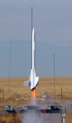
Sephydra is a scratch futuristic fighter with a beveled profile and a 7-motor cluster.
After some consideration of what to do with the big tube, I eventually decided latched on to clustering. Exactly how many motors can you cram into a 3.05-inch tube anyway? Quite a lot, it turns out. After some fiddling, I settled on 3 x 24mm plus 4 x 18mm. There are some configurations that allow more total impulse, but I didn't want to lose this craft on the first launch.
Construction:
There are few ready-made parts for this build. Loosely speaking, You need:
- Some 3.05-inch mailing tube
- Some 3/32 inch ply for centering rings and fins
- Some 24mm and 18mm motor tubes, each with an engine block and clip
- A long section of Series 175 tubing from Semroc, with a matching coupler and nose cone
- A small nose cone for the ramjets
- A recovery system
- A launch guidance system (rail buttons or lugs)
- The following additional tube assortment, all Semroc sizes:
- Series 13
- Series 11
- BT-50 (24mm)
- BT-20 (18mm)
- BT-5 (13mm)
- BT-3
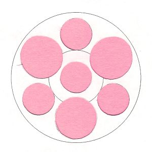
Building the centering rings took an entire week of hard work. The geometry of the rear ring was too tough for me so I used the following approach. With online and downloadable tools, I designed a non-beveled cluster centering ring by drawing three simpler versions and taping them on top of each other. These simpler starting points were patterns for 3 x 18mm, 3 x 24mm, and a central 18mm. Tracing these together I formed the round version.

(CLICK for full size images)
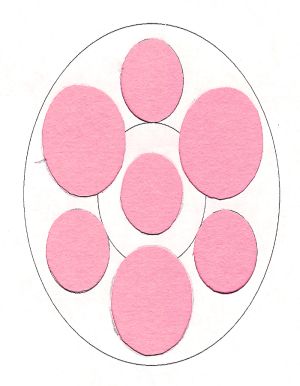
 Next, I figured out the amount of distortion that would be caused by the beveling. (This
geometry is easier after you decide on the bevel angle.) I scanned my round template into Photoshop then stretched it
vertically by the appropriate factor. Note, however, that this stretching fails to account for the fact that the holes
should also be somewhat wider. (A consequence of the beveling, I guess.) Thus, after constructing the aft centering
ring, you need to sand each hole wider until everything fits perfectly. You also need to sand a bevel on the exterior
of the ring and the interior of each hole. I've given you the template for the hardest centering rings. As a pop quiz,
try to make the other two yourself. (You need one straight Series 175 and one beveled Series 175. These two should have
holes offset to the very edge.)
Next, I figured out the amount of distortion that would be caused by the beveling. (This
geometry is easier after you decide on the bevel angle.) I scanned my round template into Photoshop then stretched it
vertically by the appropriate factor. Note, however, that this stretching fails to account for the fact that the holes
should also be somewhat wider. (A consequence of the beveling, I guess.) Thus, after constructing the aft centering
ring, you need to sand each hole wider until everything fits perfectly. You also need to sand a bevel on the exterior
of the ring and the interior of each hole. I've given you the template for the hardest centering rings. As a pop quiz,
try to make the other two yourself. (You need one straight Series 175 and one beveled Series 175. These two should have
holes offset to the very edge.)A note about the sanding: You will have holes as near as 1/32 inch apart in some places. Be very careful crafting this ring. I drilled a series of adjacent small holes around the cutting lines with my Dremel then switched to a cutting bit to clip away the tiny remnants between holes. Then a barrel sanding bit completed the job. Note how the motor tubes are beveled at the aft end.
By comparison, the rest of the rocket is easy. I do all my filling and sanding of spirals and wood before attachment. I primed periodically along the way to check for blemishes.
Cut the fins and strakes with attention to the grain direction. The angle on the main fin should match and extend the aft bevel angle. Glue and fillet. The ramjets are formed by nesting bevel cut tubes of the varieties listed above. The interior ramjet tubes extend halfway through the largest with balsa bulkeads at that point. The front half of the outer ramjet tube received a split nose cone as shown in the photos.
Cut the Series 175 tube somewhere in the middle and add a bulkhead (at least 0.75 inches inside the tube) and an attachment point for the recovery system on the upper tube. On this tube I also added a cockpit carved from balsa. On the other (lower) portion of the tube, add a coupler on the upper end. My shock cord was mounted inside this tube with a smooth dollop of epoxy putty.
 Taking the aft portion of the Series 175 tube, secure at least 3 or 4 inches of it inside the larger
tube using the remaining centering rings. Make the holes in those rings flush with the top edge of the tube so you can
further strengthen the assembly by gluing the tube itself to the inner wall of the large tube. Here are a couple of
optional ideas that I didn't do. First, you could attach the shock cord to the rings down here. I didn't do this
because I feared that the ejection from 7 motors would quickly burn through the Kevlar®.
Second, it would be possible to design a clever baffle system with the forward rings and tube, but I felt I had my
hands full already and I wanted maximum strength.
Taking the aft portion of the Series 175 tube, secure at least 3 or 4 inches of it inside the larger
tube using the remaining centering rings. Make the holes in those rings flush with the top edge of the tube so you can
further strengthen the assembly by gluing the tube itself to the inner wall of the large tube. Here are a couple of
optional ideas that I didn't do. First, you could attach the shock cord to the rings down here. I didn't do this
because I feared that the ejection from 7 motors would quickly burn through the Kevlar®.
Second, it would be possible to design a clever baffle system with the forward rings and tube, but I felt I had my
hands full already and I wanted maximum strength.
On the side of the rocket directly opposite the upper fin, I attached two brass launch lugs, 1/4 inches in diameter and 1.5 inches long. These were roughed up with my Dremel and then attached with epoxy putty to give a very smooth, seamless look.
My model needed 3oz of melted lead in the nose for stability. The center of pressure for my rocket is a bit forward of the joint between the upper fin and the corresponding strake. Get the fully loaded balancing point at least 3 or 4 inches forward of the CP. Glue on the nose cone.
Finish up the recovery system and it's all done except the painting!
Flight and Recovery:
It was a beautiful launch day in the Colorado prairie with record warmth and quite a large crowd of club members and
visitors. Fearing recovery damage, I installed a huge 42 inch X-form nylon chute. It was a very tight fit so I put the
Kevlar®
protector in alone rather than wrapping the chute with it. This proved to be a mistake. Furthermore, the chute was so
tight and filled such a great length of the tube that I was 75% sure it would not eject. I had to trust 7 ejection
charges to do their work.
 Before loading each motor, I stuffed its forward end with a little wadding to prevent any back burn.
Then the motors went in: 3 x E9-6 and 4 x C6-7. The timing delays on this combination are nearly perfect for
simultaneous ejection. I have a 4-lead clip whip, so I twisted adjacent outer ignitors in parallel pairs, with one C
and one E in each pair. The central C got its own lead.
Before loading each motor, I stuffed its forward end with a little wadding to prevent any back burn.
Then the motors went in: 3 x E9-6 and 4 x C6-7. The timing delays on this combination are nearly perfect for
simultaneous ejection. I have a 4-lead clip whip, so I twisted adjacent outer ignitors in parallel pairs, with one C
and one E in each pair. The central C got its own lead.
We found a 5 foot long 1/4 inch rod, loaded the rocket and attached all the igniters. With all the wiring cascading out the aft end, the rocket looked pretty formidable on the pad. 5-4-3-2-1-liftoff! The flight was incredible. The rocket slowly climbed up the rail and gradually gained speed, giving spectators quite a show at low altitude. The velocity and noise increased until the rocket was tearing through the sky and it was virtually out of sight. RockSim predicted an altitude of 1993 feet.
The ejection was well timed, and remarkably, the chute billowed out. Recovery was flawless. The face of the aft centering ring was seriously blackened with smoke and soot, which made it look extra cool. I found that 6 of the 7 motors had lit, with one outer C6-7 failure. The chute was a little singed so it would have been better to wrap it directly in the Kevlar® pad.
Those 7 motors cost a fair chunk of change and I had only intended one launch, but as the weather held, I couldn't resist a second flight. This flight was a mirror image of the first: slow initial ascent accelerating until it ripped skyward in a pillar of smoke and flame. Another flawless recovery and all 7 motors lit!
Summary:
Considering the design, the very complex build, and the perfect flights and recoveries, Sephydra must count as one of
my all-time favorites.
 |
 |