Scratch 19 Cubic Inch Cargo Bay Rocket Original Design / Scratch Built
Scratch - 19 Cubic Inch Cargo Bay Rocket {Scratch}
Contributed by Karl Upton
| Manufacturer: | Scratch |
How To Build A 19 Cubic Inch Cargo Bay Rocket
Design and Purpose
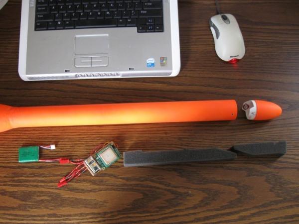
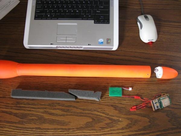
Needing a payload rocket to carry experimental flight computers/dataloggers (see article on
GPS Datalogging), I envisioned a flexible design that could be launched on any
number of motors up to a combination of five with a payload capacity of 19 cubic inches. This is more than enough cargo
space than needed for my electronic payloads but its cavernous space is utilized to adjust the rockets CG via foam
spacers used within the cargo area allowing the payload to be placed in the rear, mid or forward section of the BT-60
cargo tube. This CG flexibility is needed to fine tune the rockets changing SM ratio due to the variability in overall
rocket weight caused by the different combination of motors that can be used. The motor weight ranges from 2 –
4.5 ounces depending on which combination of 4 18mm motors and a single 24mm motor are chosen for flight.
The fins are swept behind the airframe to keep the CP as far a ft as possible. In a nutshell, the
design brings the CP as far aft as possible and keeps the CG as far forward as possible.
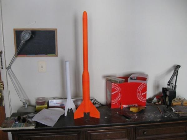
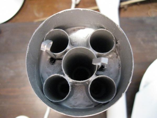
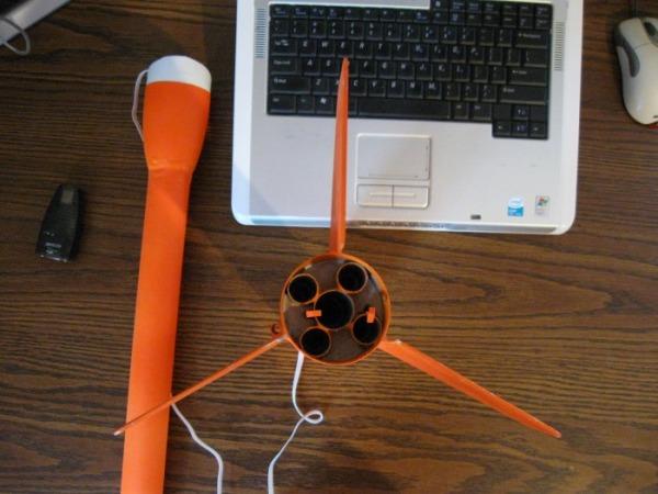
I have never built or flown a cluster design rocket, let alone one from scratch. So I spent some time reading up on rocket design and stability and based a design around the 5 motor cluster, starting with a BT-80 airframe transitioning to a BT-60 cargo tube with removable nosecone/cargo door. It will have 2 motor hooks retaining up to 2 motors; 1-18mm & the 24mm for ejection/recovery. These 2 motor tubes will have an internal baffle reducing burnt parachutes. The remaining 3 motors if used, will eject out of the rocket. This design enables the rocket to have a recovery charge available in any of the motor combinations used and keeps the recovery weight as low as possible.
General specs:
- 5 cluster motor design, TTW tri-fin, BT-80 to BT-60 transition, 3/16 launch lug
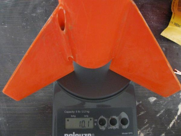
- Weight w/ recovery gear & NO motors: 10.5 ozs/294 grams
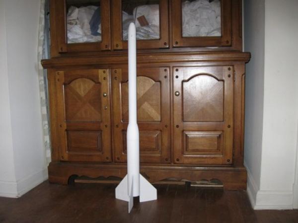
- OAL:38.5"
- Fin Area: 16 cubic inches per fin X 3
- Cargo Space: 19 cubic inches, 1.5D X 17.5”L
Naming Convention
The total amount of displacement available for thrust is 96mm; 18mm X 4 motors + 24mm X 1motor = 96mm.
Originally dubbing it a “Space Freighter,” I quickly realized it would be highly unlikely for it to venture
beyond our beloved Troposphere into space--even with 5 motors, so th SF-96 became the TF-96; Tropo-Freighter-96. Still
not satisfied, I demoted the “Freighter” designation to “Liner” due to the BT-60 transition for
the cargo space. If I kept the airframe a straight BT-80, it would have merited the “Freighter”
designation. This straight BT-80 airframe was my original design, but I quickly realized that this would be far too
much cargo space for ANY combination of low-power motors or any electronics I built. So, the final designation is
TL-96, which is short for “Tropo-Liner-96.”
Build
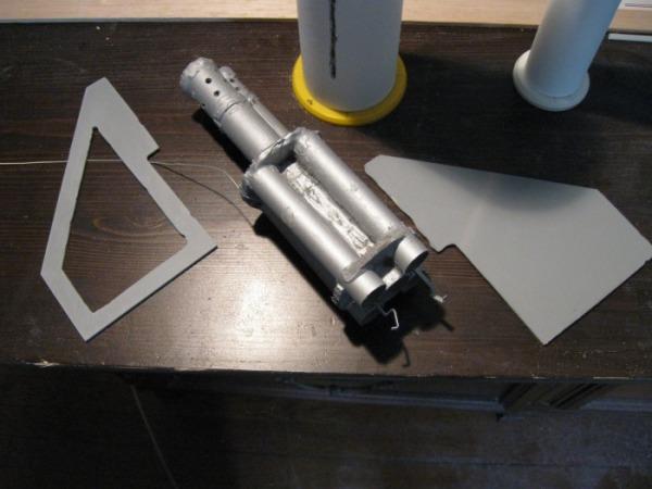
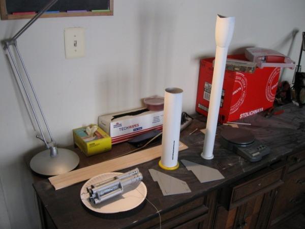
I started the build at the motor cluster. I glued up the five tubes and added the motor mount bulkheads. Then I
cut the slots for the fins and glued the motor mount in the airframe. I recessed it so the nozzles of all 5 motors were
recessed by ¼ inch. This was as far as I could recess them without burning the airframe. The 4 18mm motor tubes
are butt-up to the BT-80 airframe. Recessing the motor mount moved the CG as far forward as I could, when the massive 5
tube motor mount is fully loaded it can add up to 4.5 ozs of weight.
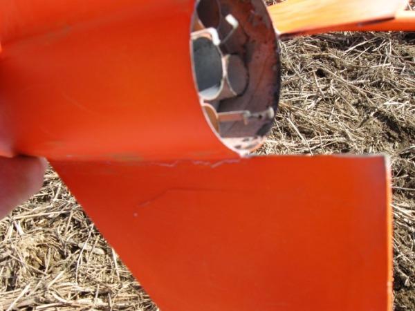
The three fins are 2.5mm ABS cored with 1/8” balsa. Due to the quintuplet motor cluster, only 2 of the fins were able to be mounted TTW, leaving the third to be surface mounted on the BT-80 tube. The aft end cluster pictures explain this better than I can write it.
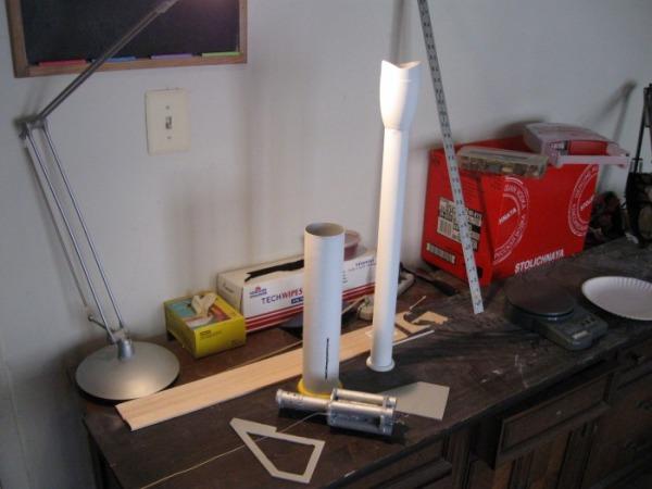
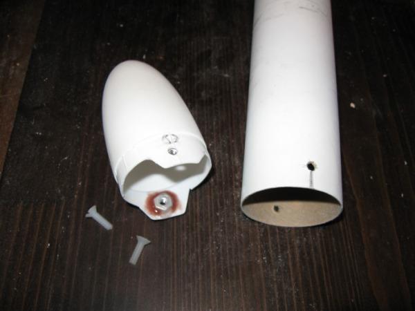
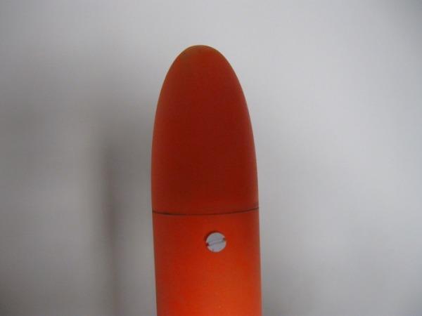
A standard BT-80 nosecone is used for a transition by removing the aft end and epoxying the BT-60 “cargo space” to its forward end. A cargo floor was added 1.5” forward of the BT-80 nosecone/BT-60 epoxy weld to maintain the BT-60s tube diameter.--Any flexing of the tube here might pop the BT-60 off of the BT-80 nosecone resulting in loss of the payload.
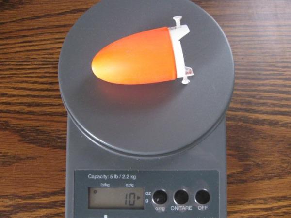
The nosecone/cargo hatch is a standard BT-60 nosecone with its aft end cut out and 2 6-32 aluminum nuts epoxied to each side allowing 2 6-32 plastic screws to retain the nosecone/cargo door in place. This modification reduces the stock 12 gram nosecone to 10 grams including paint.
A ¼ inch flat elastic shock cord is used along with a 6” X 6” Nomex parachute protector and a 24” standard parachute.
I glued up the entire project with Dollar Store 5 minute epoxy with balloon filler. I find it easier to wor k with 5 minute epoxy over anything else, due to quick cure times that allow me to crank out a rocket in the shortest amount of time. 90 second epoxy is used to “tack” parts into place, particularly fins and after this “tack weld,” 5 minute epoxy is used to for final glue-up.
Finish
Finish on this rocket was the same as all others so far; tube spirals and balsa grain were filled in with wood
filler, white primer is applied and sanded, followed by a coat of fluorescent paint which is sanded then a
topcoat of the same paint is applied and finally a coat of clearcoat is applied. This process leaves a durable surface
and is easily identified in the sky or on the ground.
Launch
The weather for 3/31/09, the day of the TL-96 maiden launch was perfect. Mid 60s, clear without a cloud in sight
and no wind. Absolutely beautiful.
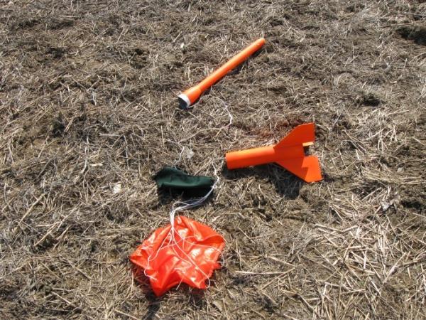
The first launch consisted of a single D12-7. I thought it had too long of a delay but that is what I had on hand for a low-impulse solo motor flight. The launch rod was angled improperly due to the weight of the empty TL-96 and after a springboard launch, it flew vertical for about 40 feet before veering into a perfectly horizontal flight for approximately 300 feet. I had given up hope for my creations survivaland waited for it to lawn dart, but the 7 second delayed recovery charge came at the LAST possible kagilasecond deploying the chute for a picture perfect 30 foot drop into the empty corn field. I recovered the rocket with no d amage and a little shocked it survived.
After modifying the launch rod/pad, I boldly loaded a D12-3 and 2 C6-3s. This launch was absolutely spectacular in its straight-as-an-arrow SLOW lift off and flight. I guesstimated its maximum altitude at approximately 500' ? straight overhead.--Almost out of sight and higher than I expected for that motor combination. The 3 second delay seemed perfect and the chute deployed as the rocket was on its side just after apogee with no problem.
The rocket came in too fast on its 24” parachute and after making a one fin landing, it popped that fin loose in the airframe.--Not off, just loose. It seems at impact, the flexible “ABS frame” of the fin flexed, while the balsa core did not, popping the epoxy joint loose. It was an easy repair to make but the rocket was grounded until then. If I had used a longer cure epoxy it might not have been damaged at all. It was a damper on my plans for the day, I had a pack of E9-4s ready to roll for the TL-96, but it wasn't going to happen. Luckily, the damage was minimal, I had other rockets to launch and I had a wonderful day.
Lessons Learned
A 24” parachute is woefully inadequate for a payload safe recovery on a 10.5 + oz rocket.--My rocket
became damaged with an empty cargo hold! I will upgrade to a single 30”+? parachute or possibly a 2 chute design,
one for the booster and a second for the cargo tube with no connection between the 2 during recovery.
My target weight for the TL-96 was 8 ounces. It finished up at 10.5 ounces. After a pre and post paint scaling of the TL-96, I figured that 2 ounces of this rockets weight or approximately 20% of its overall weight is wood filler, primer and paint! If you take away the paint factor, I was pretty much on for my weight target, I just didn't realize how heavy paint is. I could not scrape any of that paint off, but the only paint that will be applied to any future creation is as light a dusting as possible with a florescent color, no pri mer.--Just enough to see it in the weeds, that is it! The performance of this rocket would be DRASTICALLY increased by losing 2 ounces. I realize this will make for quite ugly rockets bearing spirals, pencil marks and epoxy seams, but that is the way it is from now on. It really took the wind out of my sails during the build after I realized that 20% of the rockets weight was useless paint/prep. I can say that this new method will decrease the build time of future rockets. No sanding, priming, painting and cure time will cut overall rocket assembly time by at least 25%. Not too mention a good can of spray paint/primer aint cheap either. More money for motors!
The sight of a cluster going off is awesome and I prefer to work with the lower power motors to achieve clusters and boosters rather than spend big bucks on a single higher power motor. Clusters are tricky to work with, but a scratch build of a cluster and a clear launch day will educate you im mensely on the subject.
I have many more tests to run on the TL-96 prior to its service life as a payload rocket.--I didnt even get to launch with the 62 gram ballast which represents my GPSDL which the TL-96 is designed to carry. After the repairs are made and an upgrade in recovery gear, I will update this page with the total results of the TL-96 test flights by 5/1/09. I hope to have a data article page from the GPSDL by then also.


 |
 |