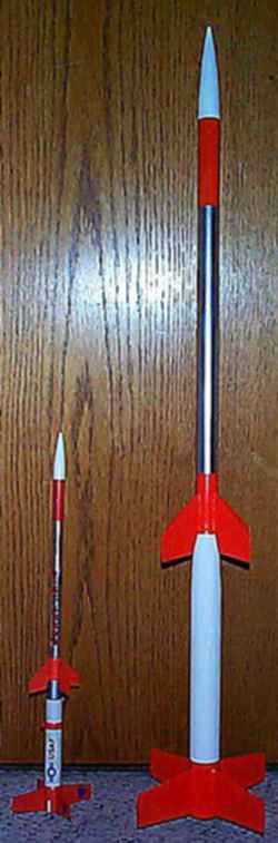
Scratch 2X Nike Arrow Original Design / Scratch Built
Scratch - 2X Nike Arrow {Scratch}
Contributed by David Fergus
| Manufacturer: | Scratch |
(Contributed - by David Fergus)
 Description:
This is an approximate 2X scale-up replica of the
Estes Nike Arrow, with coloring
and dimensions approximating the model kit rather than the real rocket. The
model has a 24mm engine mount, but can fly on as small an engine as a B6-4 with
a removable engine adapter. The parachute comes out the top attaching to the
nose cone, rather than separating at the transition like the original. This
model is 34" tall, and weighs about 3.4oz. without an engine. The fin size
and length are 2:1, but the diameter is slightly less than 2:1 due to
unavailability of exact 2:1 diameter body tubes.
Parts:
- one 18" BT-50
- one 12" BT-50
- one 10" BT-55
- one 4" white plastic NC-50(the white one in the Estes Designer's Special is perfect)
- three 55/50 heavy duty centering rings
- one 50/20 heavy duty centering ring
- one BT-50 body tube coupler
- engine hook
- shock cord
- clay
- 3/16" launch lug
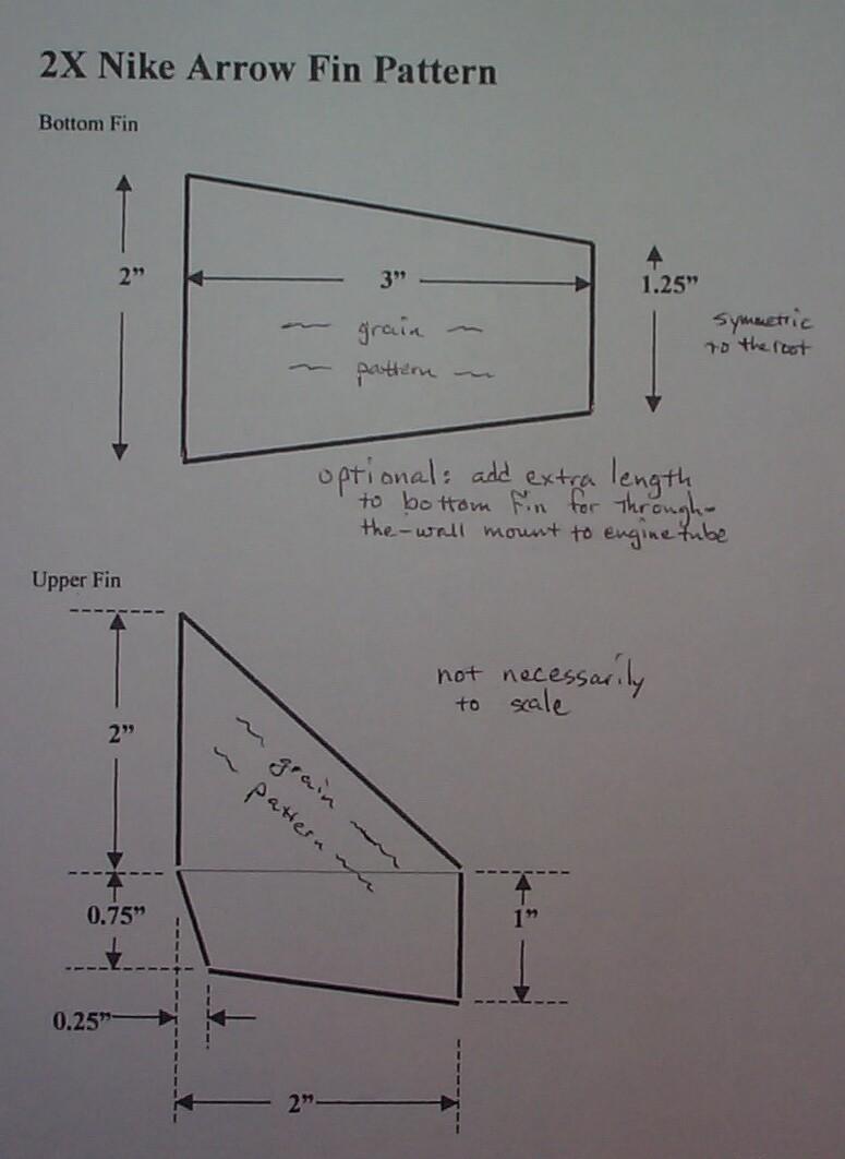
- balsa fin stock
- Fin Pattern
In addition, you will need to make an 18mm/24mm removable engine adapter if you do not have one. Use Elmer's Carpenter's Wood Glue for sandable joints and faster drying than regular white glue, and Elmer's Fill & Finish for smoothing fins, body tubes and transition shroud.
Assembly:
1. Glue one of the 55/50 centering rings part of the way into the top
of the BT-55 tube. This will be later used as a lip for mounting the transition
shroud. An optional Kevlar® shock cord could be attached to the forward
centering ring, and later threaded through into the BT-50 body tube under the
transition shroud between step 3 and 4.
2. Glue the 50/20 centering ring into the 12" BT-50 tube 2
1/2" from the rear. This will serve as the thrust ring. Glue the engine
hook into the tube with the front of the hook 2 1/2" from the rear, and
just behind the thrust ring. Glue the remaining two larger centering rings onto
the 12" BT-50 engine mount tube 1" and 2 1/2" from the rear.
3. Glue the 12" engine mount tube into the 10" BT-55 tube
so that the rear of the engine mount tube is flush with the BT-55 tube. Note
that the front of the engine mount tube will protrude out of the front
centering ring and BT-55 tube about 2".
4. Glue the BT-50 tube coupler halfway into the front of the engine
mount tube. Glue the 18" BT-50 tube into the other half of the tube
coupler. Check for straightness before the glue sets.
5. Choose thickness and strength of fin material as desired. I used
1/16" balsa for the upper fins and 3/32" balsa for the lower fins.
Measure the dimensions on the fins of an Estes Nike Arrow, and double the
dimensions, cutting out the fins with grain pattern following the leading edge
of the 4 smaller front fins, and perpendicular to the root edge on the 4 rear
fins. Make 2 paper transitions for a 2 1/4" long BT-55/BT-50 transition.
The dimensions of the shroud should be {small radius: 6.311"; large
radius: 8.568"; angle: 27.84 degrees with some extra for overlap}. (Note:
These calculational results were obtained using a shroud calc. program on
Rob Blaske's home
page)
6. Glue first one paper transition shroud, and after it is dry, a
second one. Be liberal with the carpenter's wood glue, as it is an excellent
strength enhancer after it is dry. After the transition shroud hardens, the
glue will shrink and ripple. Sand down any edges and ridges, then fill in the
ripples with undiluted Elmer's Fill & Finish, sanding to desired shape and
smoothness.
7. Make a BT-55 fin marking guide for 4 fins and a launch lug, and
mark the body tube all the way to the front of the BT-55 tube. Make a 4 fin
marking guide for a BT-50 tube, and mark the tube just forward of the
transition with the front fins in line with the rear fins.
8. Put pin holes in the body tubes and the root edges of the fins for
increased bonding strength, and glue on the fins.
9. Finish to the desired smoothness with Elmers F&F.;
10. Prime and sand. Paint the rear tube and transition shroud gloss
white. For a better looking orange, all areas that will be orange should have
one coat of white. Mask the section that will remain white, and paint the rear
fin section as well as the front fins and the entire 18" of the BT-50 tube
gloss orange. Do not remove the masking over the white section, as it will be
easier to mask for the chrome layer. Mask and paint the middle section of the
forward tube chrome, leaving the front 4" orange. It was just more masking
work than I wanted to do to paint the transition shroud silver, so I left it
white.
11. If a Kevlar® shock cord was not used, glue in a traditional paper
shock cord mount with a 3 foot shock cord.
12. Put enough clay in the nose cone to keep the CG forward or in the
middle of the front fins with the largest engine intended to be used. Prime and
paint the nose cone if required. Add decalcomania as desired.
13. Attach shock cord to the nose cone, attach a 14" parachute,
and prep for launch.
Flight:
Depending on final weight, the maiden flight should be on the
smallest engine advisable, and work your way up. For my 3.4oz. model, I first
used a B6-4, which flew straight and stable to about 150 ft. It then flew to
about 300ft on a C6-5. I haven't tried a D engine yet, as I need a bigger
field.
11/99 -
1. It flies great and straight on a D12-5 to about 1000ft. However,
since I did not do through-the-wall fin mounting, and I had forgotten to do a
glue fillet on one fin before doing an Elmer's Fill-N-Finish fillet, one lower
fin ripped off during flight on a D. The Fill-N-Finish does not work like glue!
There was enough other fins to keep the rocket stable. I recommend cutting
slots for the lower fins and modifying the fins to be through-the-wall.
2. I realized after publishing that I forgot to mention launch lugs
in the instructions. Use 3/16" lugs and glue them on just before
finishing, one down by the engine and one just below the transition.
 |
 |