Scratch AGM-65A-X Maverick Original Design / Scratch Built
Scratch - AGM-65A-X Maverick {Scratch}
Contributed by Carl Tulanko
| Manufacturer: | Scratch |
 Brief:
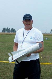
Maverick AGM-65A-X White Version True 33% Scale Length: 32" Diameter:
4" Fin Span: 14" Fin Height: 3" Est Weight: 5-6 lbs Dry Motors:
"I-J" class For the longest time, I have always had a passion for
Military Missiles; the power, their ability to maneuver and target and the
unique looks of these warbirds defending our skies have left me in awe,
watching as they perform their duty defending our country. Though they may be
an icon of freedom, missiles are a bit more difficult to duplicate in our
hobby, due their inherent but required instability. This is the challenge that
has driven me to build rockets such as the
AMRAAM,
Harpoon
and now, the TV Guided AGM-65A Maverick. The construction throughout this
article may seem a bit long, but the model is very easy to build and looks
great on or off the rail.
Construction:
Before I began, I knew this would be a heavy rocket as that is what is usually
required to make a true scale missile stable…a lot of nose weight. In
fact, for as short as it is, it wound up being the heaviest one in the group
when considering length to weight, so great care was taken to make sure it
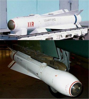
would be stable on the pad. I had planned on customizing my own nosecone,
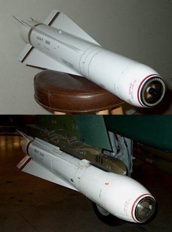
including the lens section, so after taking many pictures from WPAFB U. S. Air
Force Museum, the decal documentation was completed. They had two of these
missiles on site, one in white and one in olive drab, so I decided to build the
white TV guided version for now, but will eventually have both as I took pics
of both. Also, these pics are available to anyone wanting to build this model;
just send me an email and I will send you the pics.
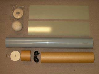 I began construction with the body tube; the
tube is PML Quantum and it uses a piston ejection system, as I have found them
very reliable when "tuned in" properly. It's designed as a basic
single deploy model and uses a dual parachute system. Main fins are TTW, while
the center fins have the lower 6" extending through the wall into the body
tube for mounting; the remaining forward part of the upper fin resides in a
"dato" slot. The Body tube was pre-slotted from PML to my
specifications, but I had to cut out the lower 6" for the upper fins all
the way through for the TTW mount as PML only dato slotted them. After this was
done, I spent some time drawing the fin patterns out on the .062" G10
fiberglass sheets I had purchased.
I began construction with the body tube; the
tube is PML Quantum and it uses a piston ejection system, as I have found them
very reliable when "tuned in" properly. It's designed as a basic
single deploy model and uses a dual parachute system. Main fins are TTW, while
the center fins have the lower 6" extending through the wall into the body
tube for mounting; the remaining forward part of the upper fin resides in a
"dato" slot. The Body tube was pre-slotted from PML to my
specifications, but I had to cut out the lower 6" for the upper fins all
the way through for the TTW mount as PML only dato slotted them. After this was
done, I spent some time drawing the fin patterns out on the .062" G10
fiberglass sheets I had purchased.
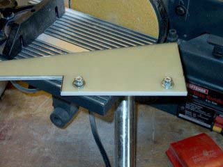 I worked on the Maverick fins next; all the
fins were rough cut with a Dremel and asbestos cutting wheel, then I stacked
the lower fin set and used a table sander to "fine" shape them. Next,
I worked on the upper fin set. I started by flushing up the bottom root and
rear, then used the table sander to shape the rear. Once this was done, I
stacked them and drilled two 1/4" holes through the bottom root of the fin
that resides inside the body tube. The fins were bolted together, then final
sanded on the table sander. All fins were ready to go and I just need to round
some edges.
I worked on the Maverick fins next; all the
fins were rough cut with a Dremel and asbestos cutting wheel, then I stacked
the lower fin set and used a table sander to "fine" shape them. Next,
I worked on the upper fin set. I started by flushing up the bottom root and
rear, then used the table sander to shape the rear. Once this was done, I
stacked them and drilled two 1/4" holes through the bottom root of the fin
that resides inside the body tube. The fins were bolted together, then final
sanded on the table sander. All fins were ready to go and I just need to round
some edges.
After I rounded the edges of the fins, I cut a small corner in the long fins tip to simulate the real ones. The motor mount was next; it was sanded and ready to go. I glued about 5" of 3/4" Nylon piston strap to the side of the motor mount using 30 minute epoxy and taped it down while it dried. This method is used on all the PML kits and shouldn’t be news to anyone who has built them.
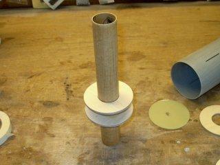 I glued on the upper
centering ring for the lower fins and the lower centering ring for the upper
fins. This way I had access to both fin areas for mounting. The CR's were
epoxied to the motor mount after carefully measuring their position. Next, I
mixed up some West Systems epoxy and installed the motor mount. While I was at
it, I took the top centering ring and added a slot for the 3/4" Nylon
piston strap. Next, I glazed it with the remaining epoxy so the top CR would be
waterproof and make for easy cleanup.
I glued on the upper
centering ring for the lower fins and the lower centering ring for the upper
fins. This way I had access to both fin areas for mounting. The CR's were
epoxied to the motor mount after carefully measuring their position. Next, I
mixed up some West Systems epoxy and installed the motor mount. While I was at
it, I took the top centering ring and added a slot for the 3/4" Nylon
piston strap. Next, I glazed it with the remaining epoxy so the top CR would be
waterproof and make for easy cleanup.
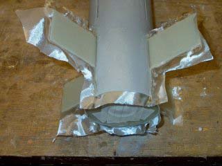 The lower fins were aligned and glued
through the wall of the body tube on to the motor mount. I fiberglassed the
inside joint on each fin side using 6 oz cloth following my normal routine,
then used some 1/4" Balsa planks to sandwich the fins between the inside
body tube wall and motor mount. The planks were cut to the length of each fin,
then rolled in epoxy and installed while dripping, so they hardened like
concrete but weigh a lot less that hardwood. It's a new technique I am trying
for inside fillet replacement. I installed a centering ring over the bottom of
the motor mount and pushed it up against the bottom of the lower fins and
planks. This fin area was now capped at both ends using CR's.
The lower fins were aligned and glued
through the wall of the body tube on to the motor mount. I fiberglassed the
inside joint on each fin side using 6 oz cloth following my normal routine,
then used some 1/4" Balsa planks to sandwich the fins between the inside
body tube wall and motor mount. The planks were cut to the length of each fin,
then rolled in epoxy and installed while dripping, so they hardened like
concrete but weigh a lot less that hardwood. It's a new technique I am trying
for inside fillet replacement. I installed a centering ring over the bottom of
the motor mount and pushed it up against the bottom of the lower fins and
planks. This fin area was now capped at both ends using CR's.
The bottom centering ring was marked using a PMR retainer as a template. Next, I installed three 8-32 blind nuts for the retainer and epoxied them into place. The very bottom G-10 centering ring was placed in a short piece of body tubing and the CR with the blind nuts was laid over top of it; this 1" deep piece of BT was my alignment jig. I drilled three holes through the blind nuts into the G-10, then used a bigger drill bit to open the holes. the G-10 CR was placed over the ply ring and it was a perfect fit as the blind nuts stuck out of the ply about 1/32" and fell right into the G10 holes. The back side of the blind nut holes were filled with wax so epoxy would not get into them during installation. I roughed up the inside face of the G-10 ring, then mixed up some 5 minute epoxy and laminated the two pieces together and clamped them until they dried.
Next, I mixed up some West Systems epoxy and applied it around the inside of the body tube and motor mount at the end. I also applied some to the inside and outside edges of the laminated CR, then poured the rest inside the bottom well of the body tube. The laminated CR was inserted into the BT, then the Bt was placed upright on a table and pushed the bottom CR assembly flush into place. I cleaned up any excess epoxy, which wasn't much, with denatured alcohol, then rolled the body tube to make sure all the glue inside would produce some good fillets.
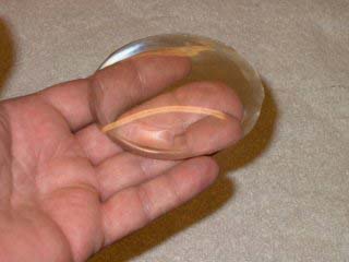
My plan was to mold my own glass window out of epoxy. First off, I want to say to you all, NEVER use acetone to thin out epoxy! My experimentation brought forth results that can only be described in a photo. I tried it with some 5 minute epoxy, and when it kicked...it KICKED! It started bubbling and rising like a cake...I LMAO. The result was a bubbly substance that actually represents expanding foam, which rose to 1" thick; looks like I found a new use for epoxy as a foam filler!
Well, I switched to West Systems 105 Resin with 206 Hardener, which is 30 minute. The 206 is less yellow than the 15 minute or 1 hour, so it was my first choice. I cleaned out my mold (bowl) from the previous attempt, then mixed up a batch and poured it in. As careful as I was with mixing, it was loaded with bubbles, so I took some denatured alcohol and poured a little into the mold, then started mixing. It got swirly at first, but then cleared up and the bubbles were dissapearing left and right. Once it was clear, the top still was not smooth, so I lightly blew on it and actually watched the alcohol evaporate to leave a glass finish. The mold was left to set overnite. Once set up, I "popped" the glass out of the mold and it came out really well. The Diameter of the lense was just under 3".
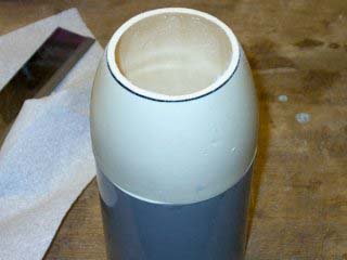
I laid the glass piece over top the nosecone,. marked it with a magic marker and sanded the glass down on it's edges to near where it needs to be for diameter. I also drilled and cut out the rear bulkhead on the nosecone so I could have some working room for the details and lead counterweight.
I took my time glassing the lower fins so I could make sure it would apply in a manner that allowed minimal sanding and still provided a scale appearance when completed. West Systems 105 resin and 205 fifteen minute hardener were used for the fiberglassing process. West really sands like a dream when compared to other epoxies I have used and it is the premier resin I use in my shop these days. I overlapped the forward area about 1/2" beyond the fin root and let the excess glass cloth overhang the rear of the body tube during the glassing process and this excess was removed. Also note that I decided to glass and sand the rear fins before mounting the forward fins; this gave me working room to sand the glassed area without fighting with the small space between the fins. Fine sanding was completed and the lower fins were ready for primer.
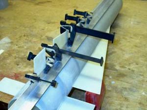 Installing the center fins on the Maverick
was next on the agenda. I used 5 minute epoxy to tack them in, then finished
the center fin fillets. In summary, I tape one end, then ran tape across the
fin and BT parallel to and about 3/8” from the joint. I poured the epoxy,
then used a piece of PVC tubing to make the fillets and wiped off the excess
from the PVC end as I went. Once done, a ridge of extra epoxy had formed from
excess epoxy spilling out the sides of the PVC tube while squegeeing and it
resided on the tape. I pull the tape off and fillets were done, with no excess
to clean up on the BT or fins.
Installing the center fins on the Maverick
was next on the agenda. I used 5 minute epoxy to tack them in, then finished
the center fin fillets. In summary, I tape one end, then ran tape across the
fin and BT parallel to and about 3/8” from the joint. I poured the epoxy,
then used a piece of PVC tubing to make the fillets and wiped off the excess
from the PVC end as I went. Once done, a ridge of extra epoxy had formed from
excess epoxy spilling out the sides of the PVC tube while squegeeing and it
resided on the tape. I pull the tape off and fillets were done, with no excess
to clean up on the BT or fins.
Eight pieces of 1/4" balsa were cut to the length of the inside 6" long area for the center fins and I made them wide enough to wedge between the inside body tube and the motor mount. The top of the motor mount was plugged with a rubber boot so epoxy wouldn't run down the motor mount. The planks were saturated with West Systems epoxy and pushed into place, then I installed the very top centering ring. I poured some more epoxy on the top of the centering ring and rolled it around to create fillets, then cleaned up any spilled epoxy. Next, I glued the Nylon strap to the Piston face plate, then glued this face plate into the Piston tube. Once it set, I glazed the inside and outside faces of the piston with epoxy to waterproof the wood and make for easy cleanup with soap and water after a launch.
I completely sanded the rocket, then did an initial fill on the body tube and nosecone. More sanding (yuk!), a tac rag and it was finally ready for primer. I started by applying 4 coats of White Krylon Primer to the body tube and nosecone. It dried overnite, then I wetsanded with 150-220 grit sandpaper. Next, I applied 4 coats of Gray Krylon Primer to the BT and NC and let them sit for two nites. I filled any pinholes, then "dry" sanded the filler with 220 grit wet/dry sandpaper. A couple of spots were touched up, then I wetsanded both pieces with 220 grit sandpaper. Some more light filling, then four more coats of White Krylon Primer were applied to both the nosecone and bodytube and left once more to dry overnight for two nites.
 I wetsanded once again under the
sink with 400 grit and moved to 600 grit wet/dry sandpaper. The nosecone was
dried, then I used a tac rag to remove any dust. Finally, 4 coats of Krylon
White Glossy Paint were applied to the nosecone and it came out pretty nice.
Next, the surface of the BT was tac ragged, then I applied 4 coats of White
Glossy Krylon Paint. The coupler holder was removed from the front of the BT,
along with the paper I had taped up inside the motor mount. Note that I now use
glossy paint for all my rockets, with the exception of a few nosecones. This
allows for a much smoother surface when applying decals, the paint is much
thicker than flat paint, which lets it fill nicer and I wind up flat coating it
afterwards anyway for that military look.
I wetsanded once again under the
sink with 400 grit and moved to 600 grit wet/dry sandpaper. The nosecone was
dried, then I used a tac rag to remove any dust. Finally, 4 coats of Krylon
White Glossy Paint were applied to the nosecone and it came out pretty nice.
Next, the surface of the BT was tac ragged, then I applied 4 coats of White
Glossy Krylon Paint. The coupler holder was removed from the front of the BT,
along with the paper I had taped up inside the motor mount. Note that I now use
glossy paint for all my rockets, with the exception of a few nosecones. This
allows for a much smoother surface when applying decals, the paint is much
thicker than flat paint, which lets it fill nicer and I wind up flat coating it
afterwards anyway for that military look.
Working from all the photos and measurements I took while at the WPAFB Museum, I spent the next day finishing the scale decals and have them available via a link. I was able to fit 2 complete sets on one sheet of decal paper...good for redundancy. One other thing I did follow was the coloring of the decals...I used my photos to "sample" the color of the real missile, so yes, even the color is exact.
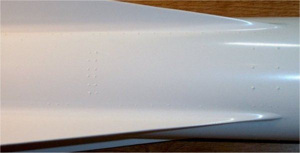
It was time to do rivets…I grabbed my syringe, some R/C canopy glue, a roll of low tack masking tape and a marker. The masking tape was applied parallel to where the rivets would reside and I measured and marked off the location of each one on the masking tape. Next, the syringe was filled with the glue; canopy glue resembles Elmers White Glue, except when it dries, it can be easily painted since it is water and oil-proof. Doing one side at a time and working from my photos and markers, I completed all the rivets on the model. If I made a mistake, the old rivot was simply "wiped" away and a new one was done. It took a few hours but, as sick as this sounds, was very enjoyable. The rivets dry in about an hour, so in no time I was spraying the final coat of Krylon White Glossy Paint over them.
After the paint dried, I masked off the bottom of the rocket and painted the brown stripe using Krylon Brown Glossy Paint. The masking was removed, then the edges were pressed down and the model was set aside.
Note that all wood parts below were glazed with thin CyA and sanded to a plastic finish before painting. Now came for the very fun and exciting part...the nosecone! This is where the heart of the missile resides and I reserved myself to do it as close to scale as possible. I started by making two Phenolic rings, one 1.5" and one 2" in diameter. Next, a large base plate was made that would cap the inside bottom of the assembly. Two other plates were made from 1/4" ply, one 1.5" plate for the camera base and one 2" in diameter that would reside below this plate and cap the bottom of the camera cavity.
The phenolic rings were filled, then primed and painted. The two smaller plates were primed, then the smaller one was painted with Testors Gold Paint and the bottom plate was painted black. I began working on detailing the gold camera baseplate. I made a support bracket from some .010 mil plastic sheet, then primed and painted it black. Three pins were cut to 1/4" in length and used to mount the bracket. A template was made and 4 holes were marked and drilled in the gold plate. No. 1 screws were mounted in the holes for realistic support of the lens assembly.
 Next, I cut out a front faceplate, angled
at the edges and marked groove marks on it in 10 degree increments. I used a
Dremel with a cutting wheel and and cut grooves in the front faceplate, then
cut out the unused center section and epoxied it in the front of the nosecone.
It was primed, then painted by hand using Testors Silver Paint.
Next, I cut out a front faceplate, angled
at the edges and marked groove marks on it in 10 degree increments. I used a
Dremel with a cutting wheel and and cut grooves in the front faceplate, then
cut out the unused center section and epoxied it in the front of the nosecone.
It was primed, then painted by hand using Testors Silver Paint.
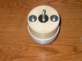
Now it was time to turn my attention to the camera. I used a 1/2" piece of wooden dowel, put it inside my drill press and used a combination of files to cur grooves in it to make the camera shaft. Notches were added to the sides for realism, then it was primed and hand painted in silver. The top of the camera was made from a piece of white plastic tube and died black using Rit Dye. I pressed it on the silver camera shaft, then filled it with 5 minute epoxy, creating a lens with the epoxy. A hole was drilled thorugh the two plates and the camera shaft and I used a 4-40 screw and epoxy to assemble the three pieces, along with the Phenolic sleeves. A CR was made for the 2" sleeve and glued to the sleeve, then the entire assembly was glued to the front plate inside the nosecone.
I spent the next few days detailing the Maverick; all the decals were cut out for the body tube, then applied using Microscale Decal Set. I also cut out very thin strips of Monokote self-stick film for the panel lines and they were applied to the model. The decals came out really nice, so I turned my attention to the nosecone. It was masked off, then the red stripe was painted using Krylon Bright Red Glossy Paint. The masking was removed and the edges were pushed down, leaving it nearly seamless. Finally, I applied the decals to the nosecone, which was a bit of a feat. Each red letter had to be individually applied to follow the curve of the nosecone, even though they were printed out as a label. Once again, Microscale Decal Set was used and the nosecone decals were completed.
Four coats of Top Flite Flat Clear Dullcoat were applied to the body tube, then it was left to dry. The nosecone was next...I masked off the upper face where the lens would attach and shot four coats of clear on it, after cleaning it first with a tac rag. Both the nosecone and body tube coated well.
 Time to finish the lens; I started by
sanding it to fit the nosecone, then lightly tapered the edge and sanded the
bottom 1/8" lip all the way around with 100 grit sandpaper for good
adhesive purchase. The top 3/16" lip was also sanded with 600 grit wet/dry
sandpaper to prepare it for painting. Masking the outer 3/16" was a
challenge; I wanted it to be a perfect circle, but without templates, you have
to "eyeball" it when masking. I wound up using some 1/16" R/C
Trim Tape for the "master" edge, then worked my way inward to the
peak of the Lens with 1/8", 1/4" and finally 3/4" masking tape.
Additionally, the bottom of the Lens was also masked using strips of 2"
blue low-tac masking tape.
Time to finish the lens; I started by
sanding it to fit the nosecone, then lightly tapered the edge and sanded the
bottom 1/8" lip all the way around with 100 grit sandpaper for good
adhesive purchase. The top 3/16" lip was also sanded with 600 grit wet/dry
sandpaper to prepare it for painting. Masking the outer 3/16" was a
challenge; I wanted it to be a perfect circle, but without templates, you have
to "eyeball" it when masking. I wound up using some 1/16" R/C
Trim Tape for the "master" edge, then worked my way inward to the
peak of the Lens with 1/8", 1/4" and finally 3/4" masking tape.
Additionally, the bottom of the Lens was also masked using strips of 2"
blue low-tac masking tape.
Once the Lens was masked off, I hit the lip that was showing again with 600 grit sandpaper, cleaned it and went to paint. Two coats of Krylon Semi-Flat Black Paint were used to paint the Lens. I knew that I only had one chance to get it right, especially with masking it and sanding, so extreme care was taken not to overdue it. I let the paint dry for about a half hour, then removed the bottom masking. It looked good so far , so The rest of the tape was removed and it worked! I had a nice 3/16" lip all the way around the Lens. I pressed the inner paint lip down and blended the ridge to the lens, which is easy to do since the paint is still soft and it was ready to mount.
Next, I worked on the nosecone bulkheads and balancing. I used the remaining BB's I had that Ken Parker gave me ( I am out Ken, please send more ). Some West Systems Epoxy was mixed, then poured into the inside front of the nosecone, around the edges. I laid the nosecone on a flat surface and poured the BB's on the rear 2" inside plate, which is the bottom plate of the camera assembly. They bounced everywhere and evenly distributed themselves around the front of the nosecone and sank into the epoxy. I set the nosecone aside to let the added lead weight set and began work on the bulkheads.
 Three plates were made for the bulkhead
assembly. The inside plate was hollowed out for access to the nose in case more
weight needed to be added. I drilled holes through all three plates, then took
the inside plate and installed two 1/4" blind nuts (T-nuts for you rocket
guys.) Next, I installed two bolts through the T-nuts so they would extend out
the back of this plate. It was epoxied into the inside of the nosecone and I
used the other two plates to assist with alignment. The outside plates were
removed, and West epoxy was poured on the inside of the bulkhead plate to add a
good inside fillet.
Three plates were made for the bulkhead
assembly. The inside plate was hollowed out for access to the nose in case more
weight needed to be added. I drilled holes through all three plates, then took
the inside plate and installed two 1/4" blind nuts (T-nuts for you rocket
guys.) Next, I installed two bolts through the T-nuts so they would extend out
the back of this plate. It was epoxied into the inside of the nosecone and I
used the other two plates to assist with alignment. The outside plates were
removed, and West epoxy was poured on the inside of the bulkhead plate to add a
good inside fillet.
The two outside plates were laminated together with West Systems Epoxy and a 850lb rated solid 1/4" "Eye" bolt was installed to hold the two bulkheads together while the epoxy set. I ran some epoxy around the edge of this assembly to strengthen it and prevent chipping, then let it dry. The plate was installed over the bulkhead to check the fit and it worked out well. It is retained to the back of the nosecone with two 1/4" nuts and 1" diameter washers and slipped right over the two extruding bolts.
Now it was time to check balance. I loaded up a 3 Grain Pro38 I205 and installed it in the rear of the model. A 15' piece of shock cord was cut from the spool of 9/16" Tubular Nylon I purchased from the ROL Auction some time ago and placed inside the body tube. I cut another 10' section, which will be used for the nosecone, and also placed it inside the tube. The model will use dual parachutes, one for the nosecone and one for the body tube; this setup has worked well for the Harpoon and helps prevent zippers, so I decided to use it for the Maverick. Quick links were added and the nosecone was installed, then the model was checked for balance.
With motor installed, CG came out to 2 1/2" in front of CP. FYI, Center of Pressure is located 12" from the rear of the model. I decided to add a bit more nose weight, so I purchased some 1/4" x 1 1/2" fender washers and stacked them on the shaft of the "Eye" bolt. The plate was bolted to the bottom of the nosecone and checked once again for CG. This time it was 4 1/2" in front of CP...I was finished with the balancing. Finally, shock cords were tied and taped; they are connected to the Piston and three quick-links.
The lens was mounted using a 1/8" wide thin film of Silicon Sealer around the mouth of the nosecone. I made sure the inside camera bay was free of dust, then cleaned the inside of the lens before mounting. I placed the lens on, twisted it a bit for a good seal and wiped up the excess. It appeared to be stuck on pretty darn good, so sanding both edges paid off.
A trip to the hardware store was required before I could mount the rail buttons. I picked up some Stainless #8 screws 1" long and some 8/32 bolts 1" long, along with some locking nuts. The hole for the lower screw was drilled and the button was installed. The upper button was installed witha bolt and I hand curved a 3/4" fender washer for the inside of the BT. The bolt was retained with a #8 self locking nut. I checked the lens and it too was ready, so I am polished up the Lens and got ready to take some final pics.
Flight:
All I can say about launch day is, well, it was hot! Fortunately, we had
humidity in the low 40% range and the breeze of 4-6mph made it tolerable. It
was time to launch the Maverick AGM-65! I assembled the Pro38 3 grain I205,
then installed it in the motor mount and used a PML retainer to keep it in
place. A dual parachute design was used; the body tube comes down under one
chute, while the nosecone comes down under it’s own parachute. I started
using this setup with my scratch Harpoon AGM-84, which also can be found in a
review here at EMRR. This deployment technique gets the heavy nosecone away
from the body tube, helping prevent zippers.
CG was checked, which was one BT in front of the CP located 12” from the rear. Then I realized that I forgot to put a pressure relief hole in the forward BT, so I broke out the Dremel and did a field drill with a 1/8" bit and located the hole 5” behind the end of the BT. My flight card was filled out and I headed to the rail. The card was turned in and I weighed the model. The nosecone came in at 1.5 lbs and the Body tube I found out later came in at 3.51 lbs without motor or chute. This brought it to over a 5 ½ lb rocket without motor and over 6 1/2 lb loaded and ready to go. The rocket was placed on the rail, the ignitor was installed and it was time for a launch.
When the button was pushed, it took to the skies, did a swirl about 200' up and continued. The flight was way cool...the swirl, then up at about a 70 degree pitch...I would have sworn a F-14 was targeting it! The delay was set to 9 seconds, since Rocksim said 10 was too much and 8 was a bit short. Well, the delay needed to be ALOT shorter, a 8 or 6 seconds would have worked. It did eject nose-down, but didn't zipper and both the nose cone and BT came in under their own chutes. I heard the nosecone land, which wasn't usually a good sign. Walking over, I found the body tube in the high grass and in pristine condition, but the nosecone wasn't quite as lucky. It landed in a gravel parking area just off the access road, but luckily, it didn't hit the road. The gravel chipped some of the paint on it's side, so a touch up will be needed, but the lens only received a minor scratch, since it obviously landed sideways. I was very pleased with the rocket’s flight, but I feel it needs a bit more nose weight and a bigger motor like a 4 grain PRo38 I240 or a AT I211W. Nosecone weight will be brought up another 8 oz and the paint will be fixed but, for as much fin as was on this bird and the unknown conditions of building a exact scale replica, I was VERY happy with the flight!!!
Summary:
 In
summary, the Maverick was a blast to build and fly! Old school strengthening
methods and basic construction of a single deploy airframe shouldn’t be
news to any HPR flier and makes this rocket very easy to build. In order to
really make it stand out though, take the time and detail the model as this
will give it features that are both unique and a real head turner. Flight
characteristics make it look just plain good in the air and the details make it
stand out on the ground. I do have a ½ scale 6” diameter version on
the boards now which will be done in the 65D Infrared Olive drab version, but
that will be another story. Much time was spent detailing a scale nosecone,
which is the heart of this bird and the results made it more than worth the
effort. Scale Mavericks are hard to find in kit form, and impossible for HPR,
but with this solid design, decals now available and the long but necessary
construction details posted in this report, anyone can easily build this
AGM-65A TV Guided Maverick!!!
In
summary, the Maverick was a blast to build and fly! Old school strengthening
methods and basic construction of a single deploy airframe shouldn’t be
news to any HPR flier and makes this rocket very easy to build. In order to
really make it stand out though, take the time and detail the model as this
will give it features that are both unique and a real head turner. Flight
characteristics make it look just plain good in the air and the details make it
stand out on the ground. I do have a ½ scale 6” diameter version on
the boards now which will be done in the 65D Infrared Olive drab version, but
that will be another story. Much time was spent detailing a scale nosecone,
which is the heart of this bird and the results made it more than worth the
effort. Scale Mavericks are hard to find in kit form, and impossible for HPR,
but with this solid design, decals now available and the long but necessary
construction details posted in this report, anyone can easily build this
AGM-65A TV Guided Maverick!!!
 |
 |