| Manufacturer: | Scratch |
 History, Airframe,
Nose Cone and Tail Cone
History, Airframe,
Nose Cone and Tail Cone
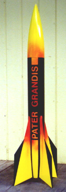
I always liked the Estes Big Daddy. I was one of the first on my block to build one. Then I wanted a bigger one a made plans to extend the body. But it is a non-standard 3" airframe. There are no body tubes or couplers on the market that will fit.
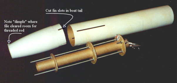
So I bought two kits. The body tubes are ten inches long. The fin slots are 4 inches long, extending 4 ½" up from the end. So I cut the tube in half (5"). The slotted half was made into a coupler by removing ¼" (taking out one of the slots). Sanding made it fit better. The new coupler then was epoxied into the top 5" tube and the top of the 10" tube. Be very sure that the coupler is low enough below the top to clear the nose cone.
Now what do I do with the other nose cone? It
wonít fit into any other rocket. Solution: a boat tail. Cut the base off
1-1/8" from the shoulder and cut the tip off 6" from the shoulder.
Test fit the tail cone into the aft end of the body tube. Mark through the
slots onto the part of the tail cone showing through the slots. This material
must be removed.
Parts List
- 2 ea. Estes Big Daddy Kits
- 1 ea. 12" Vaughn Brothers 29mm Motor Tube
- 1 ea. Launch Lug, 5/16" brass tube (1/4" ID, 5" long)
- 2 ea. #8-32 x 12" Threaded Rods
- 16 ea. #8-32 hex nuts
- 2 ea. #8-32 cap nuts
- 3 ea. 1/8" Quick Links
- 2 ea. 3/16" x 1-1/2" Eye Bolts
- 1 ea. 1/16" Wire Cable
- 2 ea. Cable Ferrule and Stop Set
- 1 ea. 1/8" Aircraft Plywood (12" x 24" sheet)
- 2 ea. #8 washers
- 2 ea. 1/4" washers
Motor Assembly
- 3 centering rings 1/8" plywood (cut fins first (see "Fins" below) fin layout is critical))
- All with 32 mm center hole
- Aft ring 60 mm diameter
- Center and forward rings 74 mm diameter
- Two 5/32" holes in each ring, 22 mm from center, 180 deg. apart
- Two 3/16" holes in forward ring, 27 mm from center, 90 deg. from first two holes
IMPORTANT NOTE:
The rods must NOT line up with the fin slots. A 45
deg. offset would be optimal.
I unfortunately achieved closer to 30 deg. But it will
work.
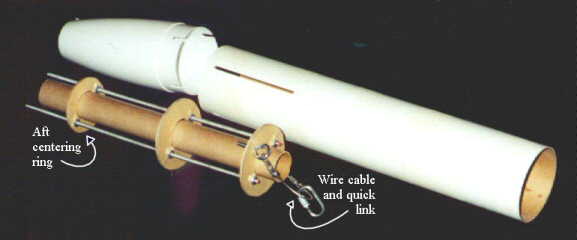
The aft centering ring at set 2-3/4" up from the end of the rods. Fix a nut on each side of the ring on each rod (four total). Secure with a drop of CA on each nut. Thread a nut from the top of each rod, down towards the aft ring. Temporarily place the motor tube into the aft ring so it protrudes 2-1/4" past the ring. Slip the center ring over the assembly. Lower the whole assembly into the tail cone. The aft ring should be snug in the tail cone. The rods should extend 1/2" beyond the bottom of the tail cone. Settle the center ring on the top of tail cone. Lower a nut on each rod down to the center ring. Remove the assembly. Raise the other nuts up to the bottom of the center ring. Tighten, test fit and secure with CA.
Secure the two eye bolts into the two 3/16" holes in the forward ring. Tighten and secure with CA. Sting a loop of wire cable securing with ferrules. Thread a nut over each rod and slip the forward ring onto the rods. Thread a nut over each rod. The forward ring must be at least 11" from aft end of rod. Tighten and secure with CA.
Test fit assembly into tail cone and then slip the body tube on, making sure everything lines up. Sand centering rings as necessary.
Remove body tube, motor assembly, and motor tube, making alignment marks as you go. Epoxy the motor assembly into the boat tail. Epoxy the motor tube into the motor assembly. The end of the motor tube should be flush with the end of the boat tail.
I then attached a quick link onto the wire cable with 9 feet of braided Kevlar®(TM). Then glue the motor assembly and the tail cone into the aft end of the body tube. Carefully mind the alignment marks.
Motor Retention
I had originally intended to use modified Kaplow Klips cut from 1/4" brass stock. But the #8 threaded rod was just too big for a 1/4" brass strip. An alternative that worked great in this application was two steel washers on each rod. I used four hex nuts and two cap nuts on the threaded rods. The stack on the rod is comprised of (from fore to aft) two hex nuts (for spacing), the 1/4" washer, the #8 washer, and the cap nut. May I also suggest putting the nuts in place BEFORE you begin painting. This will keep the threads clean.
 Fins and Launch
Lug
Fins and Launch
Lug
Print the fin patterns on heavy paper stock. Each fin is in two pieces. Cut a total of four fins. I used 1/8" aircraft birch plywood. Poplar or even basswood may be good enough, but I tend to over build. I tried to get the patterns to work on a 6" x 12" sheet, but I couldn't get an efficient layout. I then found a 12" x 24" sheet in the hobby shop. It worked perfectly, and I now have a lot of scrap for future projects. As a matter of fact, it would probably be prudent to cut the fins out before the centering rings.
Sand the fins and test fit in the body tube and the two pieces together. Sanding will most likely be required for an ideal fit. Attach the fins with epoxy.
Attach launch lug to body tube along side one of the fins.
CP and CG
Using RockSim I was able to determine stability for probably the largest engine I would use on this rocket, an H128. I added 5 ounces of weight in the nose to achieve stability.
Click on Image to see RockSim
Recovery
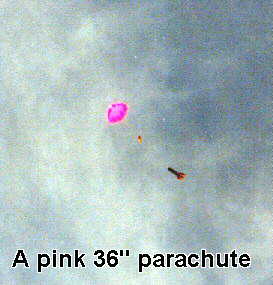
Calculations show a 45" parachute to be the best size for a rocket this heavy. But my 45" parachute is a little big for this rocket. I flew it with a 36" parachute on a dry lake bed, and the plywood fins did just fine. As noted above, the shock chord is 9 feet of braided Kevlar®(TM).
Was It Worth It?
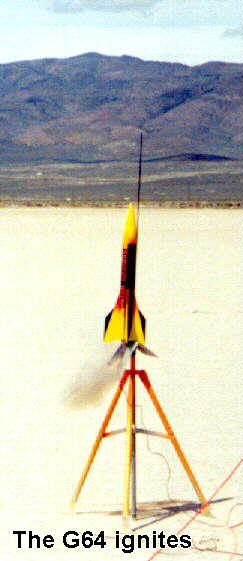
I orginally set out to build an affordable 3" model. I thought kitbashing would achieve this goal. Looking back on it, I realize I ended up spending more than some 3" kits are being sold for. On the other hand, I think it looks better, with its boat-tail and long fins, than most vanilla 3" rockets. So, was it worth it? I guess it depends what you're after. Fo me it was. Especially when the rocket I designed screamed skyward on a roaring smoke-belching G64.
Take a look at some launch pictures!
The G64
Lights!
A pink 36"
parachute
Landing 16 feet
from the launch pad!

Contact me
If you have any questions or comments, I would like to hear from you. My e-mail is r-james@worldnet.att.net
 |
 |