Scratch ARC IRIS (1/2 Scale) Original Design / Scratch Built
Scratch - ARC IRIS (1/2 Scale) {Scratch}
Contributed by Scott A. McCluskey
| Manufacturer: | Scratch |
Note: This is a slightly condensed version of all the information that Scott has produced for his Level 3 project. Visit his site to read the additional information and enjoy additional pictures.
Brief:
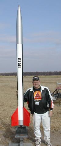
My Level 3 project was a: Scratch-Built Atlantic Research Corporation 1/2 scale
IRIS 6" in diameter by 10' tall Launched on a Aerotech M1315.
 Nose
Cone:
Nose
Cone:
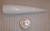
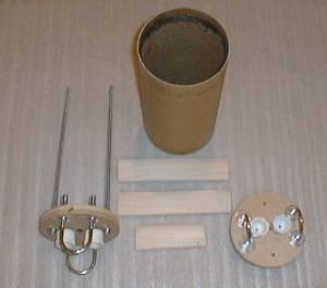
The nose cone for the IRIS is a 6" fiberglass nosecone from
Public Missiles. In the picture you will see the fiberglass
nosecone, the coupler, bulkhead, and the PML supplied U-bolt used for recovery
system attachment. The coupler, bulkhead, and u-bolt have been assembled using
epoxy.
The nose cone will not be attached to the main recovery harness and will return to earth under it's own 36" parachute. The deployment bag for the main parachute will also be attached to the nose cone and will be removed from the parachute when the nose cone is ejected.
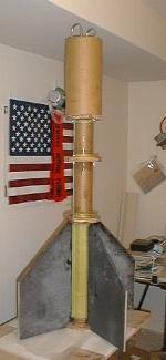
Airframe:
The body tubes are 6" flexible phenolic from
Giant Leap Rocketry The airframe consists of three sections.
The three sections are 42, 30 and 24 inches long. The 42" section will
contain the 3" motor mount and forward coupler used in the zipper-less
coupler design. The 30" and 24" sections will be connected together
using the coupler containing the electronics bay. The 24" section will
house the shock cord and Rocketman R24 drogue chute deployed at apogee. The
30" section will contain the main 168" custom parachute from
Sphereachute and recovery components.
The three airframe tubes have been covered with a layer of 6 oz. carbon fiber and 2 oz. fiberglass using RAKA epoxy products. The tubes were covered using the vacuum bagging process described by John Coker.
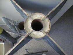
 Fins:
Fins:
The fins are made from 3/8" Baltic Birch plywood. The fins are exactly 1/2
scale based on measurements from Peter Alway's book "Rockets of the
World" Third Edition. Each of the four fins are reinforced with one layer
of 6 oz. carbon fiber and one layer of 3 oz. fiberglass using
RAKA epoxy products. Each fin
has been vacuum bagged to ensure a complete bond between the plywood and the
reinforcement materials.
Motor Mount:
The IRIS flew on a 75mm Dr. Rocket 75/6400 motor and an
Aerotech
M1315 reload.
The motor mount consists of the following components:
- 1 Aeropack 75mm Quick Change Motor Retainer
- 1 3" X 36" flexible phenolic motor mount
- 4 3/4" X 5 ply centering rings reinforced with two layers of 6 oz. fiberglass
- 2 1/4 -20 all thread rods with washers, lock washers, and nuts on either side of the centering rings.
- 1 6" X 12" phenolic coupler lined with two 6" X 6" phenolic airframe pieces
- 2 14" X 1/4-20 all thread rods to connect bulkhead to coupler
- 14 1/4" nuts, lock washers, and flat washers
- 1 3/4" 5 ply bulkhead
- 2 1.25" u-bolts for recovery system attachment
- 2 1/4" wing nuts with washers.
 The 75mm motor mount
has been epoxied into the 42" airframe section and has been reinforced
with two-part hobby foam.
The 75mm motor mount
has been epoxied into the 42" airframe section and has been reinforced
with two-part hobby foam.
Just before the motor mount was installed into the final position, epoxy was injected into the airframe above each centering ring. The motor mount was then slid into it's final position and more epoxy was injected into the airframe to form fillets on the centering rings/airframe epoxy joints. After the epoxy set up, the fin can was turned over and epoxy was again injected into the motor mount above the centering rings to form fillets on the other side of the centering rings.
Prior to final painting, screws will be used to mechanically fasten the motor mount into the airframe.
Recovery:
I purchased a custom 168"
Spherachute parachute
to use for the main parachute. The 168" parachute I had made for the IRIS
has alternating panels of white and neon orange for high visibility. The main
parachute was packed into a Rocketman deployment bag which was removed from the
parachute when the nose cone is ejected. The nose cone was recovered with a
36" Spherachute made with alternating panels of neon orange and white to
match the main parachute.
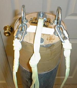 The harness are
constructed using:
The harness are
constructed using:
- 10 ft of 5/8" Tubular Kevlar® from Pratt Hobbies
- 4 ft of 1/4 Tubular Kevlar® from Pratt Hobbies
- 2 1/4" 880 lb Quick Links
- Fisherman's Knot and Figure Eight Knot described in an article by Patrick Floyd in the November 1999 issue of High Power Rocketry.
The harnesses are constructed by first tying a 1/4" Quick Link to each end using a Fisherman's knot. I am using the Fisherman's knot because the more you pull on the knot the tighter it gets. After the knots are tied, I use 1/4" Tubular Kevlar® to wrap the lose end and give the harness a finished look. The final step is to tie a loop in the middle of the harness using a Figure Eight knot.
Electronics:
Recovery electronics will consist of the following: (1) Missile Works RRC2 set
for drogue deployment at apogee and mains at 1200' A Blacksky ALTAAC 2A for
backup drogue deployment and flight data gathering. A Missile Works Wireless
Recovery Controller 2 (WRC2) for redundant backup for the main recovery system.
 Electronics Bay The electronics bay for the IRIS is built inside a
6" X 12" long phenolic coupler. The first step in building the bay
was to epoxy two 5.5" couplers inside the 6" coupler. The first
5.5" coupler was cut lengthwise and then epoxied equidistant from either
end of the 6" coupler. After the first 5.5" coupler dried, a second
5.5" coupler was cut lengthwise and epoxied in place inside the existing
5.5" coupler. When the second 5.5" coupler dried, a 6" o-ring
was set in place on each end of the bay using J-B Weld to form a gasket between
the inside couplers and the bulkheads. 3/4" 5 ply bulkheads are being used
in the electronics bay. Two 1.25" u-bolts have been added to the bulkheads
to provide attachment points for the recovery system. Two 1/2" threaded
caps are attached to the bulkheads to hold the custom ejection charge holders.
The bulkheads are bolted together using 1/4 X 20" all-thread. The three
pieces of poplar in the picture will be epoxied inside the coupler. The two
9" pieces will each contain six 8-32 T-nuts which will be used to bolt the
upper airframe sections together and also allow for access to the electronics
bay and ejection charges. The 3" piece will be used in mounting the two
key switches used to arm the altimeters. A 3/16" X 5" X 10"
electronics mounting board has been built to slide over the all-thread rods and
provide a mounting surface for the recovery electronics.
Electronics Bay The electronics bay for the IRIS is built inside a
6" X 12" long phenolic coupler. The first step in building the bay
was to epoxy two 5.5" couplers inside the 6" coupler. The first
5.5" coupler was cut lengthwise and then epoxied equidistant from either
end of the 6" coupler. After the first 5.5" coupler dried, a second
5.5" coupler was cut lengthwise and epoxied in place inside the existing
5.5" coupler. When the second 5.5" coupler dried, a 6" o-ring
was set in place on each end of the bay using J-B Weld to form a gasket between
the inside couplers and the bulkheads. 3/4" 5 ply bulkheads are being used
in the electronics bay. Two 1.25" u-bolts have been added to the bulkheads
to provide attachment points for the recovery system. Two 1/2" threaded
caps are attached to the bulkheads to hold the custom ejection charge holders.
The bulkheads are bolted together using 1/4 X 20" all-thread. The three
pieces of poplar in the picture will be epoxied inside the coupler. The two
9" pieces will each contain six 8-32 T-nuts which will be used to bolt the
upper airframe sections together and also allow for access to the electronics
bay and ejection charges. The 3" piece will be used in mounting the two
key switches used to arm the altimeters. A 3/16" X 5" X 10"
electronics mounting board has been built to slide over the all-thread rods and
provide a mounting surface for the recovery electronics.
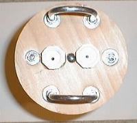 The IRIS
will utilize a redundant recovery system. Pictured is the forward bulkhead of
the electronics bay. I am using 1/2" PVC threaded caps as ejection charge
holders. I drilled a 1" X 1/4" deep hole into the bulkhead to hold
the threaded caps. I used my Dremel to grind away a small portion of the outer
threaded cap so that I would have a tight fit in the hole. After the threaded
cap was shaped to fit, I epoxied the caps in place. A 1/4" hole was
drilled through the cap and the bulkhead to allow the ejection charge leads
into the electronics bay. The caps will now act as ejection charge holders for
the ejection charges.
The IRIS
will utilize a redundant recovery system. Pictured is the forward bulkhead of
the electronics bay. I am using 1/2" PVC threaded caps as ejection charge
holders. I drilled a 1" X 1/4" deep hole into the bulkhead to hold
the threaded caps. I used my Dremel to grind away a small portion of the outer
threaded cap so that I would have a tight fit in the hole. After the threaded
cap was shaped to fit, I epoxied the caps in place. A 1/4" hole was
drilled through the cap and the bulkhead to allow the ejection charge leads
into the electronics bay. The caps will now act as ejection charge holders for
the ejection charges.
Ejection charges are built using 1/2" threaded male adapters. The first
step is to epoxy a 7/8" section of 1/2" dowel rod into the fitting.
Once the epoxy is dried, drill a 1/8" hole through the dowel to pass the
leads of the electric match. Before installing the electric match, enlarge the
1/8" hole to 3/8" by
 1/2" deep to
accept the green protective cover of the DaveyFire electric match. Once the
holes are drilled epoxy the electric match in place. I always make sure to
twist the electric match leads together as a safety precaution!!! (I like
leaving the green protective cap in place and filling it with FFFFg powder
which makes an ejection charge inside the ejection charge.
1/2" deep to
accept the green protective cover of the DaveyFire electric match. Once the
holes are drilled epoxy the electric match in place. I always make sure to
twist the electric match leads together as a safety precaution!!! (I like
leaving the green protective cap in place and filling it with FFFFg powder
which makes an ejection charge inside the ejection charge.
Once the ejection epoxy has dried, I fill the cavity with FFFFg black powder with a charge that I determined using the BP tools in the Rocketry Online INFO Central.
The ejection charges for the IRIS will be:
- 2.10 grams FFFFg black powder for the apogee charge
- 3.33 grams FFFFg black powder for the main recovery charge
Once the black powder charge is in place, I use facial tissue to make a wadding to cover the charge. I then use a candle and melt wax over the wadding and seal the ejection charge.
When preparing for launch, I pass the electric match lead through the hole in the threaded cap and into the electronics bay. I screw the 1/2" male fitting into the 1/2" threaded cap. At this point I start using my altimeter preparation checklist to ensure that I connect the ejection charge leads to the altimeter in the safest manner possible!
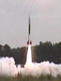 SUCCESSFUL LEVEL 3 FLIGHT!
June 23, 2001
Whitakers, NC.
Rocket - Scratch 1/2 scale ARC IRIS
Weight - 60 lbs
Motor - Aerotech M1315
Altitude 6270 feet
A special "Thank You" to my wife for not complaining about being a 'rocket widow" while I was building the IRIS and for laughing and smiling when we were hanging out in a cow pasture in North Carolina on flight day!
 |
 |