Scratch Arming Switch (for under 2 bucks) Original Design / Scratch Built
Scratch - Arming Switch (for under 2 bucks) {Scratch}
Contributed by David Lang
| Published: | 2010-05-19 |
| Manufacturer: | Scratch |
 Construction:
When building my level1 rocket, I wanted to use a simple, reliable arming switch to turn on my altimeter. My first thoughts were to use an interior switch which could be accessed through a hole in the avionics bay, but decided that it would be difficult to turn on and off especially once on the launch pad. I nixed the pull-pin type some people construct with a micro switch since it was complicated, bulky and heavy, and I know I would lose the pull pin at the launch site necessitating dismantling the rocket just to turn off the electronics.
So I decided on an external switch. It had to be low profile to minimize drag, be light in weight, and easy to turn on or off with a screwdriver. I considered the popular 110 -220 volt arming switch that is commonly available. It had the advantage of two sets of contacts (2 poles) which I did not require and uses a slotted screwdriver to activate. The disadvantage is that the markings are 110–220 instead of ON-OFF, it needs quite a large hole in my 3” rocket, and the slot to operate the switch is very short but wide. Most any screwdriver I have on hand makes a sloppy fit in this slot. Also it isn’t as low profile as I would have liked. I decided against it.
Searching the web, I located a very nicely made screw switch for 2 bucks and ordered one. To my surprise it was constructed with solid core hookup wire which is prone to fatigue and breakage. Every time the avionics bay is accessed the wires would be subject to severe bending stress. Not reliable enough for my rocket which took many hours and dollars to build. Also the supplied steel screw was not low profile, as it had a domed head.
At that point with only days to go to my Level 1 attempt, I decided to make my own arming switch based on the screw switch I have just mentioned. So off I went to my local ACE and Aubuchon hardware stores both of which carry tons of every imaginable screw, fitting and doodad in their fastener isles. You know those wonderful pull-out drawers with all their little compartments. I spent way too much time looking at all the stuff I never new existed!
While looking for the right parts, I came across the drawer of Rawl nuts©. (Some stores carry WELLNUT brand) These are top hat shaped rubber plugs that have an integrated brass nut at the narrow end. They are used for securing items to most any material by inserting into a pre-drilled hole and then screwing in the appropriate size screw. The screw pulls the integrated nut closer to the flanged end expanding the diameter of the plug which tightens it in the hole. But I digress here. The shape of the Rawl nut was perfect and it already had one highly conductive brass insert molded into the narrow end. My idea was to find another threaded brass insert to screw or glue into the flanged end, leaving a gap between the existing insert and soldering stranded wires to the two nuts. Inserting a low profile stainless steel truss head screw would connect the two inserts completing the circuit.
I selected a 6-32 thread Rawl nut which happens to be 5/16” OD (45¢) and a 6-32 x ½” pan head stainless steel Philips screw (29¢). You could also use an 8-32 or 10-32 size but I wanted mine as small as possible.
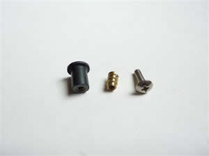 After some searching through the parts drawers I found a brass 6-32 threaded insert (55¢) that many rocketeers use to attach rail lugs and motor mounts to plywood rings. The coarse outside thread made it a very tight fit in the Rawl nut but I felt it could be sanded down to fit.
Back home I planned how I would assemble the switch. I needed to get a wire from the threaded insert at the flange end down to the narrow end without increasing the overall diameter of the Rawl nut so it would still pass through a round hole. I decided the best way to do this was to grind a channel into the rubber and one side of the integrated nut to allow the wire to be recessed. The other wire would connect to the other side of the integrated nut.
Directions:
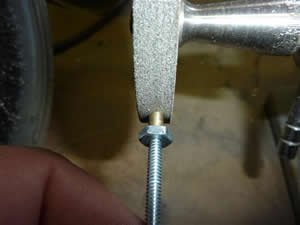
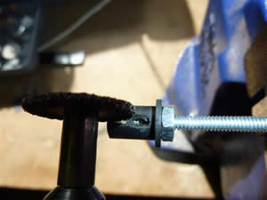
1. Reduce the diameter of the threaded insert so it is a snug fit in the Rawl nut. I used a 6-32 all thread rod and a jam nut to secure the insert to hold it for machining.
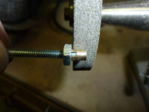
2. Shorten the insert so it doesn’t touch the integrated nut when inserted into the Rawl nut. The gap between both brass nuts should be about 1/8”.
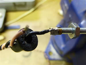
3. Using the all thread rod and jam nut to secure the Rawl nut in a vice, grind into the Rawl nut with a Dremel tool to expose its integrated nut and create a channel for the wire that will attach to the brass insert that you previously prepared. The channel should extend from just behind the flange all the way through the integrated nut and out to the rear.
4. Strip and tin 1/8” of stranded wire and pass through the side of the channel in the Rawl nut and out the flanged end as shown. Solder the wire to the brass insert you have prepared.
5. Push the insert into the Rawl nut until it is flush with the front flange. This photo was actually taken after the switch was completed.
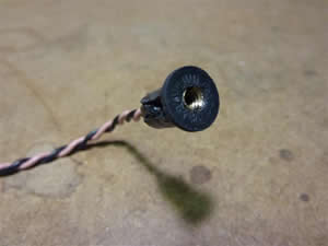
6. Thread the all thread through the brass insert until it screws into the integrated insert. Don’t force it! You may have to rotate the front insert slightly so the threads are orientated correctly to allow the rod to screw through both inserts. Use a slotted screwdriver to engage the slot in the brass insert to rotate it then try again until just right. If you skip this step, the threaded rod will not thread into the integrated nut and will just try to push the two nuts apart. You’ll know when its right as the all thread will effortlessly pass through both nuts.
7. With the all thread rod still in place, wick some cyano adhesive between the rubber Rawl nut and the brass insert. DON”T GET GLUE IN THE THREADS! Once set, withdraw the all thread for the next step so it does not act as a heat sink.
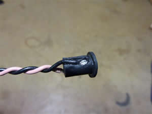
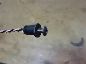
8. Strip and tin 1/8” of another wire. And solder it to the integrated brass nut. Your finished switch should look something like this:
9. Hook up the other ends of your two wires to a continuity tester and insert the 6-32 x ½” pan head screw into your new switch. At first there should be no continuity until the screw bridges both brass inserts.
10. Check your work and make sure everything looks OK. You may need to add some cyano adhesive if any part of the rubber sleeve of the Rawl nut is not secured to the two brass inserts.
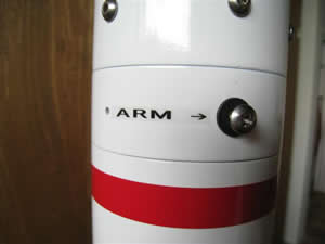
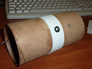
11. Drill an appropriately sized hole in the switch band of your avionics bay so that the switch snugly presses through. My hole turned out to be 21/64”. Finally wick some cyano adhesive in from the back for a perfect installation and label with a P-touch.
Copyright © by Dave Lang
 |
 |