Scratch Bad to the Bone Original Design / Scratch Built
Scratch - Bad to the Bone {Scratch}
Contributed by Ray King
| Manufacturer: | Scratch |
Brief:
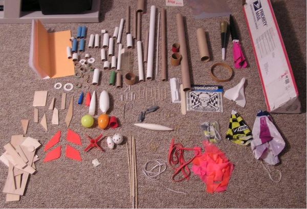
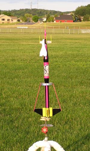
Bad to the Bone is my submission to the “Box of Stuff” contest. This rocket flies on a 24mm engine. Upon
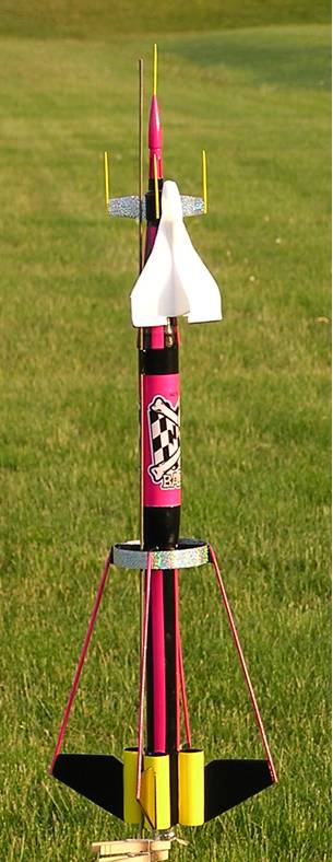
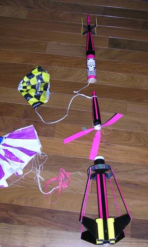
ejection the rocket separates into 4 components: main body, upper body, escape pod, and internal payload. The main and
upper body sections deploy parachutes, the escape pod is a glider and the internal payload is helicopter recovery.
Construction:
- 1. 1 - Big Bertha Nose Cone
- 2. 1 - Plastic BT 5 Nose Cone
- 3. 1 - Estes Cosmic Cobra Nose Cone with Helicopter Blades
- 4. 1 - Birthday Horn
- 5. 1 - 7.0” BT60 Tube
- 6. 1 - 13.5” BT56 Tube
- 7. 4 - 3.0” BT50 Tube
- 8. 1 - .5” Wide 3.85” OD Tube
- 9. 2 - .5” Wide Tongue Depressors
- 10. 2 -1” long launch lugs
- 11. 4 - .125” Diameter Bamboo Sticks
- 12. 6 - Wooden Tooth Picks
- 13. 1 - BT5 Plastics Fan Can
- 14. 18” 150# Kevlar® Shock Cord
- 15. 24” 1/4” Elastic Shock Cord
- 16. 1 - Small Styrofoam Glider
- 17. 2 – BT 56 to BT50 Centering Rings
- 18. 1- 3.0” 24mm Engine tube
- 19. 1/8” Balsa
- 20. 1 oz. Nose Weight (BB’s)
- 21. 1 - Bad to the Bone Decal
- 22. 1 - Sparkle/Glitter Decal
 Construction:
Engine Mount:
Start with 3.0” – 24mm engine tube; marking the centering ring location roughly.75”-1.0” from each end. On the top centering ring notch it slightly for the Kevlar® shock cord. Now tie the Kevlar® cord around the center of the tube and mount the centering rings. Make sure to pull the shock cord through the notch and push up tight to upper centering ring. I would recommend putting a bead of glue directly over the top of the cord at the joint between tube and centering ring.
Fins Construction:
The fins are cut from 1/8” thick balsa per template A. The leading edge should be rounded.
Launch lug assembly:
There are 2 – 1/8” launch lugs each 1 inch long. One attaches to the main body assembly between the mock engine tubes and the second attaches to the upper body tube assembly.
The launch lugs require standoffs. Cut 2 standoffs from 1/8” balsa. The main body launch lug standoff should be cut to .25” X 1.0”. The upper tube assembly launch lug standoff should be cut to .060” X 1.0”. Each standoff is mounted to the lugs using 5 minute epoxy.
Main Body Transition:
The main body transition is made from the Big Bertha nose cone. Drill a .25” hole in the center of the nose cone; now drill a .5” hole enlarging the hole. Next, I use my Dremel tool to enlarge the hole to fit the main body tube. Do this carefully and make sure you do this evenly. The hole needs to remain in the center of the nose cone.
Main Body Tube Assembly:
Start with the main body tube (BT56) and cut it to13.5” length. Mark the tube with 4 lines 90 degrees apart. The lines should run the length of the tube. They are for the mock engine tubes, fins, and ring supports. Now add a 5th line exactly between 2 of the other lines. Mark this line as the launch lug line. At this point the main body tube should now have 5 lines. Now draw a line around the tube perpendicular to the 5 lines. This line should be 2.5” from one end of the tube (mark this as the top of the tube).
Now, mark the 4 - 3.0” BT50 tubes with lines 180 degrees apart. Next, mount these 4 tubes (mock engine tubes), one on each of the lines on the main body tube. The engine tubes should mount flush with the bottom of the main tube. Make sure they are straight and align with the main body tube. Once dry add generous fillets between the body tube and mock engine tubes – I like to use 5 minute epoxy for this.
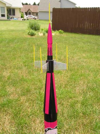
Next, the fins can be mounted on each of the engine tubes. Align the fin to be flush with the bottom of the tubes. See pictures to ensure they are installed in the correct orientation. Once dry add generous fillets between the fin and the tube.
Next, mount the main body tube transition. Slide the transition on to the tube in the correct orientation. Slide it down to the mock engine tubes. Now apply a liberal amount of glue above the line (I used 5 minute epoxy) and slide the transition up until it is even with the tube. Make sure the transition is straight, otherwise the upper tube assembly will not be straight.
Now take the tongue depressor; cut the radius ends off and cut it into 4 -1 inch lengths. These can now be mounted on the 4 lines in line with the fins. The mount the tongue depressor directly under the transition and once again when dry add generous fillets using 5 minute epoxy.
Last but not least – mount the engine tube assembly in the main body leaving about .5” of the engine tube sticking out the end of the rocket. Make sure the Kevlar® shock cord extend out the top end of the tube. Attach an additional elastic shock cord and 18” plastic parachute to the Kevlar® shock cord.
 Upper Body Tube Assembly:
The upper body assembly is made up of: party horn, plastic fin can, nose cone, 5 tooth picks, launch lug assembly and BT60 tube.
Start by mounting the plastic fin can to party horn with 5 minute epoxy. Also, use 5 minute epoxy to fill in the top gap between the fin can and the party horn. Now, take the nose cone and cut off the area that would typically go into a body tube. Next, drill a .125” hole thru the very tip of the nose cone. I have found this is typically easiest to drill from the inside out. Now, mount 1 of the tooth picks in this hole with 5 minute epoxy. I also, spread a thin coat of epoxy on to the tooth pick to strengthen it as much as possible. Note: it is very likely this tooth pick could break on recovery so you may choose not to add this feature – I believe the aesthetics are worth some maintenance. Now, the nose cone can be mounted to party horn.
After the fin can and nose cone have dried mount one tooth pick on the end of each fin – see pictures.
The final step is to attach the shock cord. I used the traditional Estes approach for this on this section of the rocket. A 12” plastic parachute is attached to the shock cord.
Center Ring Assembly:
Mark the 3.85” OD ring as if you were mounting 4 fins 90 degrees a part on it. Now, cut 4 pieces of 1/8” balsa per Temple B. These can be glued on each line in the same orientation. The fin support rods will mount to each of these.
NOTE: Read the painting and finishing section before doing this step. Now mount the large ring to the ring supports on the main body assembly. Once this is dry the bamboo support rods can be mounted to the edge of the fins and ring adapters.
Escape Pod Assembly:
The escape pod glider is a Styrofoam glider similar to those used in on the FlisKits Tri-Glide rocket. The only thing required is to add a tooth pick to secure the glider during lift off. Cut a tooth pick in half and coat with Styrofoam safe CA. The tooth pick should be placed in the center of the front support of the glider. During launch the toothpick will rest inside launch lug of the plastic fin can at the top of the rocket.
Payload Assembly & Painting:
The payload is the Estes Cosmic Cobra nose cone with helicopter recovery so no real assembly was required – only adding the rubber bands – see flight prep.
Finishing this required sanding the molding parting line and until the entire nose cone was smooth. I applied 2 or 3 coats of automotive gray primer sanding in between each coat with 400 grit sandpaper. Next, I applied a Hot Pink Pearl (Model Master #4643) after this dried. I masked the stripes and applied gloss black (Model Master #4695).
 Painting & Decals:
The Estes the Estes Cosmic Cobra nose cone really inspired the color scheme of this rocket – I liked on the pink blades really contrasted with the black nose cone. I painted the entire rocket prior to adding the center ring and ring supports. I would highly recommend this approach.
First, I filled all the balsa components, sanded and filled until they were completely smooth. Next, I applied a couple of coats of primer sanding after each. I painted the entire rocket Hot Pink Pearl (Model Master #4643). After masking the mock engines I applied the Cadmium Yellow (Model Master #4611) to the mock engines and the tooth picks on the upper fin can. Next, I masked and applied gloss black (Model Master – 4695). After the black had dried for about 48 hours I added the Bad to the Bone decal and the sparkle decals to the upper fin assembly and center ring. The final step was to apply 3 coats of Krylon Acrylic Crystal Clear #1303.
Flight Prep:
Prior to the first flight I decided to do the spin test and had to add an ounce of nose weight.
Payload flight prep is pretty simple; add rubber bands to activate the bands when free from a body tube.
The big question was how to get the payload (Estes Cosmic Cobra nose cone) out of the upper tube of the rocket. I decided to add a loop to the upper shock cord roughly 5-6” from the end of the tube (see picture). The loop wrapped around the very tip of the nose cone; the thought was that the shock cord would pull the payload out when the parachute opened up.
Here is my recommended approach: Prep a D12-3 engine, add the igniter and tape in place (no launch lug). Add a handful of “dog barf” and stuff to the bottom of the main tube assembly. Now roll each parachute and load the lower assembly parachute and then the upper parachute both in the main body tube assembly. Next, load the payload into upper tube assembly (hooking the tip of the nose cone into the loop of the shock cord). Now carefully and neatly stuff the remaining shock cord into the main body tube and slip the upper and main tube assembly together. Finally, the escape pod (glider) hangs from the launch lug on the plastic fin can at the very top of the rocket.
Flights:
I was very pleased with all 3 flights; the launches were straight even with the extra mass of the glider. The rocket hit apogee and then ejection. The glider separated and flew like a champ. The payload started to spin and although not as fast as a competition helicopter it was spinning. Next, I saw both parachutes open and drift to the ground. The flight of the glider was incredible about 70-80 seconds. The second flight was also very good; however, the glider was lost on the local school – Bummer!! The third and final flight was also good even without the glider. I need to find out where to buy more gliders!
Summary:
Pros:
The four recovery pieces keeps you busy watching their descent. The escape pod (glider) performed much better then I expected.
Cons:
The tooth pick at the tip looks great, but broke after the first flight – I think I will make this a press-in component that can be removed prior to a flight or is at least very easy to replace.
Other:
Overall this was a great project – the “Box of Stuff” was a bit intimidating when all the parts were
laid out on the floor. After, coming up with the concept, things just seemed to flow together. I was very please with
flights and can’t wait to buy more gliders. Thanks to EMRR and Todd Mullins for putting this contest together.
GREAT WORK!!!
 |
 |