Scratch DEEP-SHT Original Design / Scratch Built
Scratch - DEEP-SHT {Scratch}
Contributed by Layne Pemberton
| Manufacturer: | Scratch |
DEEP-SHT stands for:
Deep Earth
Explosive Penetration - Subterranean Harmonic
Technology.
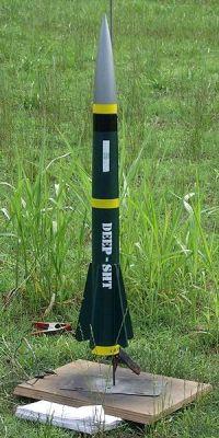
OK, I know that is a lame excuse but you have to admit the acronym makes a great name! DEEP-SHT is a military styled, single stage, sport flyer patterned after Air to Surface missiles from around the world. She is equipped with a 29mm motor mount and brought back to Earth via a 36" PML parachute deployed by a PML piston ejection system. The motor is retained by Kaplow Klips and the five fins are surface mounted foam core to reduce weight.
Check out Pemberton Technologies for more details.
The inspiration for DEEP-SHT came from my first attempt at mid-power rocketry, a now defunct little rocket called the Penetrator that I cobbled together from supplies on hand. Naming DEEP-SHT came in one of those flashes of mad, sweaty inspiration that the meds are supposed to prevent. The long, tapered design gave the impression of a probe, thus originally the Penetrator, or a missile designed to penetrate the Earth and destroy reinforced subterranean bunkers. Then a thought flashed across my minds eye, "Boy, the combatants housed in those bunkers would be in deep @$%* if this was real." The light bulb went off in my head. That was it! With that idea in mind, I reverse engineered a suitable acronym.
Construction:
The build was not difficult but was rather time consuming with all the
intermediate steps, fillets, cursing, curing times, and on-the-fly
engineering.I used the following parts:
- 1 Public Missiles, Ltd. PNC-2.56 plastic nose cone
- 1 sheet of poster board for the transition, ~.0313" thick
- 1 16" piece of Public Missiles, Ltd. PT-2.5 phenolic airframe tubing
- 1 16" piece of Public Missiles, Ltd. PT-3.0 phenolic airframe tubing
- 2 3-2.5" birch plywood centering rings
- 2 1.1-3" birch plywood centering rings
- 1 1.1-2.5" birch plywood centering rings
- 1 Public Missiles, Ltd. PIS 2.5 piston ejection system
- 1 36" Public Missiles, Ltd. parachute (borrowed from my PML Bull Puppy)
- 10ft of 9/16" tubular nylon for the shock cord
- 1 14.5" piece of Public Missiles, Ltd. PT-1.1 29mm phenolic motor mount tubing
- 5 fins cut from 1/4" foamboard
- 2 Kaplow Klips and 1/2" T-nuts
- 2 1" long x 3/8" diameter brass tube launch lugs
- 1" locking ring for parachute attachment
- 1 sheet of 1/4" plywood
- DAP Fast 'N Final Lightweight Spackle
- Several cans of Krylon primer
Before we begin, as a rule be sure to finish all epoxy joints (when possible) with heavy fillets throughout construction. This is so I won't have to repeat it through the entire article. The nose cone, airframe tubing, ejection piston, parachute, and motor mount tubing were purchased from the PML webstore. Their products and services are superb. A visit to the local hardware store provided T-nuts and the Elmer's Urethane Glue. Bondo Marine Epoxy, 1/4" plywood, locking ring, and other finishing supplies were all shoplifted from the local Home Depot. (Just kidding!)
The fins were cut from 1/4" foamboard that had been lying around looking for a way to be useful and centering rings were cut from 1/4" birch plywood. Construction began by epoxying the 2.5-3" centering rings onto the 2.5" airframe tube, one at the base and one 4" up from the base. After curing, the 2.5" tube was epoxied into the 3" tube with the upper centering ring flush with the end of the 3" tube and leaving 12" of the 2.5" tube exposed. The T-nuts are inserted and epoxied into pre-drilled holes 180 degrees apart in the aft 1.1-3" centering ring. Be careful not to get any epoxy in the threads of the T-nuts. Prior to installing, I coated the threads and heads with petroleum jelly. On to the motor mount, notch one 1.1-2.5" centering ring for the piston strap and epoxy about 4" of the 1/2" piston strap to the fore end of the motor tube according to the PML instructions. Once the strap has cured, smear epoxy around the fore end of the motor tube, slide the notched ring over the strap, and seat flush with the fore end of the motor tube. The 1.1-3" centering rings are now mounted on the motor tube, the one containing the T-nuts 5/8" from the aft end and the other 11.75" from the aft end, epoxy into place.
When the motor mount has cured, drop the piston strap back through the motor tube to keep it out of the way. Smear Urethane glue just inside the aft of the of the 3" tube, just aft of where the 2.5" tube terminates inside the 3" tube and just inside the aft of the 2.5" tube for the 1.1-2.5" centering ring. (You will need a long dowel or something similar the reach these areas.) Now that you, the table, your shoes, the floor, the cat, your significant other, and hopefully the rocket are covered with sufficient amounts of adhesive, slide the motor mount into place. The aft ring containing the T-nuts should be recessed about 1/2" from the base of the airframe, the upper 1.1-3" ring should be flush with the aft end of the 2.5" tube and the 1.1-2.5" ring should be snug inside the 2.5" tube. Spin the airframe in your hands a few times to distribute the adhesive. Stand the airframe upright on a piece of wax paper and use a 1.2" block of scrap to support the aft centering ring and allow to cure overnight. To forego the 1/2" block, I balanced the airframe atop an undersized tube covered by wax paper allowing the weight of the airframe to press the centering rings into place. The use of urethane glue is covered in EMRR's Tips/Hints Glue page. I find its strength and expanding properties perfect for the bonding of centering rings and motor mounts. The next morning when all was cured, I poured a thin layer of epoxy into the base of the 3" tube over the aft centering ring to just below the head of the T-nuts. Stand upside down until cured. This will set up with glass smooth surface and provide strength and protection for the aft centering ring. Again, do not forget to protect the T-nuts and threads with a coating of petroleum jelly.
The template for the 2.5-3" transition was produced by VCP, traced onto poster board and cut out. Be careful when rolling poster board as not to crease it. Begin by wrapping it around oversized tubes and progress down to the desired diameter. A 1/4" strip of poster board the length of the transition was cut and glued along one edge allowing a 1/8" overhang. Once dry, adhesive was applied along the overhang and connected the two edges. Press along the seam inside the transition onto a flat surface using a large dowel or similar item until dry. While dry fitting the transition, it became stuck in place and I was unable to remove it without creasing the poster board. Suddenly the "Mission Impossible" theme was playing in my head and I began to improvise a way to epoxy it into place. This was done by drilling a small hole about an inch from the base of the transition and pouring epoxy inside the transition with the help of an improvised funnel. When convinced that there was enough epoxy inside to do the job I inserted a short piece of wooden dowel to block the hole and spun the airframe a few times to distribute the adhesive evenly. The 2.5" portion of the transition is held by friction only.
The five custom fins were cut from the pattern printed by RockSim, aligned along the airframe with a fin wrapper produced by VCP, and secured with epoxy 9/16" from the aft of the rocket. Once cured, the launch lugs are attached midway between two of the fins, one 15.9" from the base and the other 3.125" from the base. Be sure to check alignment using a launch rod or dowel and once cured, fillet heavily.
To protect the PML piston from ejection gases, I poured a layer of epoxy over the top of the bulkhead, and covered the underside with urethane glue. One thing I wish PML would do is to provide decent attachment points for a shock cord. My remedy is to cut two slots into the base of the nosecone just large enough for the shock cord to pass through; finally the shock cord was tied through the nosecone slots and to the D-ring of the piston. Tie a loop in the parachute shroud lines and hook on to the 1" locking ring, the ring is then secured into a loop tied in the shock cord about 18" from the nosecone.
Finishing:
All dents, dings, gaps around the transition, and any other unsightly blemishes
were filled with DAP Fast 'n' Final Lightweight Spackle and sanded smooth. Let
it be known to all how much I hate to sand and seal. Over the years I have used
Pactra sanding sealer, white glue, urethane dope, CA, and various other
substances and have cursed them all. To date, the DAP spackling is the easiest,
fastest, and most user friendly of any sealer I have tried and is available in
quantities as small as 16oz. Go, right now, to a hardware store and ask for DAP
Fast 'n' Final Lightweight Spackling. Buy it. Use it. Love it.
DEEP-SHT was painted Krylon Forest Green. I couldn't find olive drab and decorated it in military fashion with various warning labels, serial numbers (all printed on clear water slide decal paper), yellow roll bars, and stripes. The nosecone got a yellow stripe at the base and the remainder was flavored Krylon metallic Bright Nickel. Finally, a big white DEEP-SHT was crudely spray painted along both sides of the airframe using a stencil to imitate typical military markings. A healthy layer of clear coat was shot on to protect the decals and brighten the paint colors. To my great dismay the clear coat completely killed the bright shine and depth of the Bright Nickel nosecone. ARGH! Much later I ran across a tip EMRR's Tips/Hints Finishing page warning against the use of clear coats and metallic paints. Live and Learn.
Flights:
RockSim puts the CG at 24.23" the CP at 29.92" and the mass at
~36.2oz when loaded with an F40-4W or a F52-5T, either of which should take her
to ~600' and that would be perfect for a first flight on a small field. The
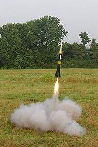
first flight was on a F40-4W and it was perfect. She flew arrow straight and
was rock solid stable. Ejection was at apogee as predicted, however, the
24" chute wasn't enough and she landed hard slightly damaging one fin. The
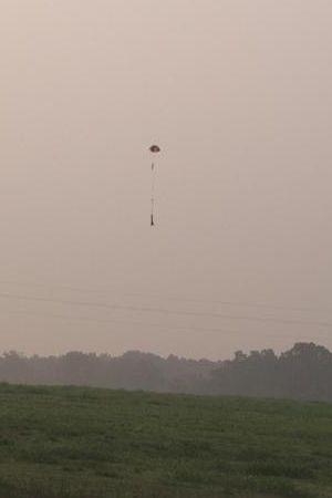
second flight was on an F52-5T and it was also solid, stable, and perfect
including recovery. Replacing the 24" chute with a 36" chute proved
to be exactly what the doctor ordered. Unfortunately, the F52 lacks the
satisfying roar and plume of white smoke put out by the F40 so I know what she
will fly on from now on. The third flight was on an F40-7W. From the
simulations I could see that this delay would be pushing the safety margin just
a bit but there was some wiggle room and I am flying from a small field
surrounded by Tree Monsters. At lift off she roared from the pad and arched
over a bit from launch rod whip so it did not quite make 600'. She reached
apogee, came about and started her descent fast and hot. It is amazing how long
seven seconds can be in Rocket Years. On the count of 8 or 9 I was calling out
to any deity that would listen to save my creation from lawn darting. Someone
must have been listening as at the last second, less than 100 feet from the
ground, the nose cone popped, chute deployed, and she landed light as a feather
without any damage. Whew!
 On the next
wind free day I will stuff her with a G64 and see what happens.
On the next
wind free day I will stuff her with a G64 and see what happens.
My experience with Copperhead igniters has not been a pleasant one. So far I have had a 50% failure rate even using the tips on EMRR's tips/hints page. No matter how much I scraped or even when I separated the leads there was still a 50% failure rate. Out of frustration I ordered two packs of FirstFire igniters from redarrowhobbies.com. The igniter failure rate then dropped to zero, however, the thought of paying almost three dollars for an igniter makes be break out in hives.
Summary:
This design is solid, stable, and loves to fly, but a lot of extra mass came
with all that epoxy. Being stranded in the outback of Arkansas, I have yet to
gain my Level One certification so I designed DEEP-SHT with a 29mm motor mount
which will loft her not very far. Had I been sane at the time, I would have
built in a 38mm motor mount and used a 29mm adapter until such time as I gained
my Level One certification, which is what I have done with all my heavy designs
since. Using foam core as fin material may seem questionable, but at the time
it appeared to be a good idea. The point was to save weight off the aft end of
the airframe eliminating the need for nose weight while still having an
acceptable CP-CG relationship with a mass compatible with mid power 29mm
motors. To save the fins from damage, I mounted them up the airframe from the
base so they wouldn't take the shock of recovery. They are still in place but
already show creases, bends, and signs of wear. The next DEEP-SHT build will be
DEEP-SHT Lite with a reduced mass, a 38mm motor mount, and sturdier fin
material.
 |
 |