Scratch Explorer 1 Original Design / Scratch Built
Scratch - Explorer 1 {Scratch}
Contributed by Ray King
| Manufacturer: | Scratch |
Brief:
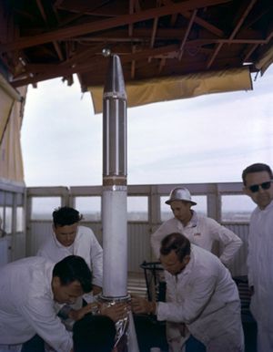
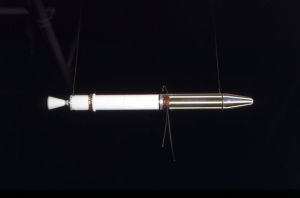
I chose to model the Explore 1 satellite as part of EMRR Challenge 2008 – Simulation Challenge. Explorer 1
(officially titled at NASA as satellite 1958 Alpha) was the first Earth satellite of the United States, launched on
February 1, 1958. Since this was my first real experience with RockSim, I thought it was fitting to model the first
satellite launched by the US. My Explorer is designed to launch using an 18mm engine and deploys an 18-24"
parachute. Scale factor of 4.528 results in a rocket 17.83" long.
Construction:
The parts list:
- 1 BT-60 balsa nose cone
- 1 #10 screw eye
- 1 BT-55, 5.44" long
- 1 BT-55, 13.197" long
- 1 BT-20, 5.0" long
- 3 centering rings BT-20 to BT-55
- 2 exterior centering rings
- 3 fins 0.030" thick clear Lexan fins
- 18" of 175# Kevlar® string
- 24" of 0.375" elastic shock cord
- 18-24" plastic parachute
- Cardstock
- Launch lug (if desired)
As I mentioned above, this was my first real experience with RockSim to design a rocket from scratch. I downloaded the demo version without issue. Having seen others use it I was pretty familiar the functionality. It didn't take long to get the hang of it and I was off and running. I modeled the Explorer I with multiple motor options and settled on C6-5 which produced an altitude of roughly 750ft at a speed of 217 ft/sec. This seemed reasonable to me so on to the build.
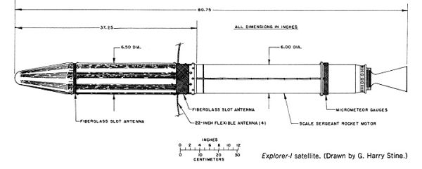
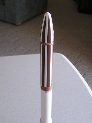
If you look closely at the drawing shown, the there are 2 different diameters of tubes on this rocket. I decide the best way to handle this was to start with a BT-60 nose cone and sand it the desired diameter and shape. In this case the software was a lot easier to make these modifications than sanding down the BT-60 cone. OK, enough whining-–I sanded the balsa nose cone into the diameter and shape I wanted. Next, I secured the screw eye to the nose cone with 2-part epoxy.
The rocket is made up of 2 different diameters of tubing so I cut the 5.44 tube lengthwise and wrapped it around the top section of the 13.197" tube. I filled the seam with Elmer's Wood Filler and sanded it smooth. This took 2 or 3 times to completely eliminate the seam.
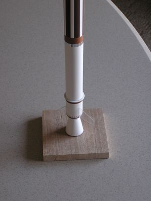
Next, I added to centering rings to represent the "MicroMeteor Gauges" (see pictures).
The engine tube is 5" long. I mounted 2 centering rings, the first one 1" from the end and the second 3" from the same end. This sub-assembly was glued into the body tube on the smaller diameter. I pushed this subassembly into the main body so the second ring was flush with the end of the tube.
I used the EMRR shroud calculator to help make the two cones used to form the engine cone. The first one is 1.32" diameter by 0.50" long and the second is 1.50" diameter by 1.60" long. Each fits over the BT-20 tube. I cut out and glued the cones together. The cone assembly was mounted to the BT-20 tube, then I epoxied the small cone to the BT-55 tube. After this was dry, I slid a centering ring onto the BT-20 and into the large cone. This ring will help support the cone.
The original plan was to attach the Kevlar® shock cord to the engine motor mount, however, I forgot to do this. I will secure the Kevlar® cord to engine prior to installing the engine. I prefer either of these methods over the traditional Estes mount. I will use an 18" Mylar parachute for recovery for a nice slow descent.
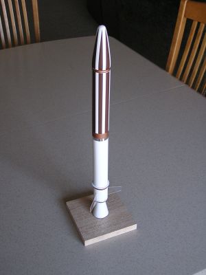
Finishing:
Finishing started with filling the tube spirals and balsa nose cone with Elmer's Wood Filler. This took a number of
coats sanding each smooth. Next, I added a couple of coats of white primer. Next, I used Tamiya Acrylic White Gloss
(X-2) for the base coat. Once this was dry I masked the top section and painted Red Brown (XF-64). Next, I masked for
the copper and painted these areas with Dark Copper (XF-28). After the copper was dry I attached 3 clear Lexan fins.
Finally, I clear coated the entire model.

Flight and Recovery:
It was basic flight prep with only one slight modification. The Kevlar®
shock cord was tied around the motor prior to installing the motor. I inserted the motor (Estes C6-5) and taped it in
place with Mylar type. Next I added wadding, rolled the parachute, and stuffed the lines. It was 7 degrees when I flew
this rocket so I covered the parachute in baby powder to avoid deployment issues.
I am not a big fan of launch lugs because of visual appearance as well as performance impact. I planned to launch his rocket from a tower launcher to eliminate the need of a launch lug.
Launch was perfectly straight, probably very close to the RockSim calculation of ~750ft. Apogee occurred and the parachute ejected. The parachute only opened partially, I assume due to the cold, by the time I reached the rocket the parachute was fully open after blowing in the wind for a few minutes. The rocket came in fairly fast and broke a fin off on landing. Minor repairs are needed and the rocket will be ready to fly again.
Summary:
The actual flight results mimicked the RockSim results. I wasn't able to confirm the altitude numbers, but I would
say they were pretty close. RockSim allowed me to change and adjust the rocket design as well as engine size until the
design was stable. This was a big advantage over my previous technique of trial and error. I have added the latest
RockSim release to my Christmas list.
PROs: Rocket looks great, flies great, and RockSim allowed me predict the results prior to wasting any time build a design that won't fly.
CONs: None.
Sponsored Ads


 |
 |