Scratch Falling with Style (FWS) Original Design / Scratch Built
Scratch - Falling with Style (FWS) {Scratch}
Contributed by Ray King
| Manufacturer: | Scratch |
 Brief:
This is my entry for the EMRR “Spaceship Design Contest – 2008”. I was very glad that EMRR offered
this contest again this year. My plan was to build 2 or 3 of these, but as many things go I was only able to finish one
of them. Without further delay here is the story (and building instructions) of the FWS. Again, this year my daughter
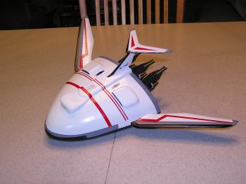
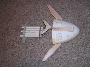
is credited with naming my rocket. I chose to model the EA Kestrel Shuttle. My original plan was to make this a glider
recovery and after one of the prototype flights my daughter said it flew like Buzz Light Year. I didn't really
understand until she said it really wasn't flying, it was “Falling with Style”. So FWS (Falling with Style)
was born.
Construction:
Component Description:
- .030” Thick Polystyrene Sheet
- 3/32” Balsa Sheet
- 1/4” Balsa Sheet
- 15” - 1/8” Diameter Wood Dowel
- 2 - BT20 – Spacer tubes – 5.75” long
- 2 - BT20 – Outboard motor tubes – 7.50” long
- 1 - BT20 Center motor tube – 8.50” long
- 2 - 18mm Motor spacer tubes
- 1 - 1/8” Launch lugs
- 36” - 175 # Kevlar® String
- 24” - .375” elastic shock cord
- Nose weight
- 24” plastic parachute
- .030” Diameter Dacron Cord
- Card Stock
- Mylar Tape
- Plans/Vacuum Forming:
- Ray's Templates
The first step was to layout the design and determine its size. I chose 18mm motor because they seemed like the right size based on the large engine cones. In addition, 18 mm engines would provide enough power to get the rocket to a reasonable altitude.
Initial Construction of the Vacuum Formed Body
The body was constructed using to polystyrene sheets, vacuum formed into the appropriate shape. I have included pictures of the foam masters used to make the top and bottom halves. Each of the vacuum formed shapes were trimmed after forming and test fit. Leave extra material on the backside, during the final assembly this will be trimmed after the main tube body is slid into it. Attaching the 2 halves is pretty tedious, take your time and be patient. The better they fit at this point the less work you will be doing during the finishing process. I used thick CA to tack the halves in place and then 5 minute epoxy on the inside and outside of the seam. Be careful not build up too much epoxy otherwise, you will be sanding it off later.
Main Body Tube Assembly
Start with the 1/8” balsa and cutout the aft support member (Template A) and the forward support member (Template B). Cut the holes for the tubes a little small. You want a tight fit between the support members and tube assembly. Since these are very dependant on the shape of the body these templates are provided as a starting point. Depending on how much you trim from the vacuum formed parts these parts may require sanding to fit better.
Now sand half of the round cross section of the 15” - 1/8” wood dowel. This will be used to form the 3 parallel lines on the back side of the aft support member. Cut the dowel into 3 pieces 4.75” long and round the ends. Next glue these to the aft support member. I used a couple tooth picks to maintain the spacing between each. Cut the dowels that cover each hole.
Next, start by marking each tube with a line down the length of the tube, one on each side of the tube 180 degrees apart. On the 8.50” and 7.50” tubes mark a line 1.5” from one end of the tube (aft support member location). Now glue the 5.75” tubes to the 8.50” on the 180 degree lines with the end of the 5.75” tubes on the aft support member line. Once the glue is dry mount the 7.50” tubes to the 5.75”. The 7.50” tubes should line up with the front of the 5.75” tubes and opposite end (motor end) of the 8.50” center tube. Once the glue assembly is complete I recommend a bead of epoxy between each tube.
 Now it is time to
add the aft and front support members. Again be patient, this will take some time. Start with the aft support member,
open the tube holes just enough to allow the tubes to slide through. The aft support member should slide up to the
bottom of the 5.75” tubes. Next do the same thing with the front support member, slide it on to all of the tubes
about .25”. Next slide the entire tube assembly into the vacuum formed shell assembly so that the aft support
member is completely in. Mark the location of the aft support member on vacuum formed assembly. Now carefully remove
the tube assembly. This should provide the location of the front and aft support member. If things fit to your
satisfaction, epoxy both support members in place. If not, try again you may need to sand the front support member to
fit better in the vacuum formed body assembly.
Now it is time to
add the aft and front support members. Again be patient, this will take some time. Start with the aft support member,
open the tube holes just enough to allow the tubes to slide through. The aft support member should slide up to the
bottom of the 5.75” tubes. Next do the same thing with the front support member, slide it on to all of the tubes
about .25”. Next slide the entire tube assembly into the vacuum formed shell assembly so that the aft support
member is completely in. Mark the location of the aft support member on vacuum formed assembly. Now carefully remove
the tube assembly. This should provide the location of the front and aft support member. If things fit to your
satisfaction, epoxy both support members in place. If not, try again you may need to sand the front support member to
fit better in the vacuum formed body assembly.
Now add the shock cord. Drill a 1/8” hole through the front support member between the center and 5.75” tube. See picture. Next, mount the launch lug. I made a mistake at this point and you can correct it. If you look at the picture I mounted the lug in the joint between the center and next tube; however, when you add the engine cone assembly there is no room for it due to the launch rod. So I recommend moving the launch lug to the top of the 5.75” tube which will allow you to clear the engine cone. Drill a hole in the aft support member that lines up with the launch lug and then use a thin wire to locate the hole on the front support member.
Final Body Assembly
 The wings and the
rudder assembly can be cut out of the appropriate balsa thickness:
The wings and the
rudder assembly can be cut out of the appropriate balsa thickness:
- Wing – Template C – 1/8” Balsa
- Tail Wing – Template D – 1/8” Balsa
- Vertical Support – Template F – 3/32” Balsa
- Square accents – 1/32” balsa
- Center Tail wing accent – 1/32” balsa
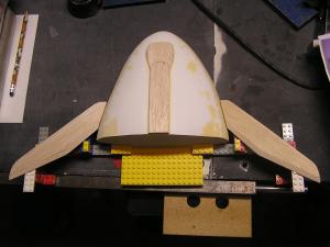
I found out how critical the wing mounting was after a number of test flights. Again, this can be tedious so be patient. Insert the main tube body into the vacuum formed shell. Slide the entire rocket on to a wood dowel that is mounted to a flat base. Make sure the dowel and base are perpendicular and the dowel fits tight into the center engine tube. Now set this on a flat surface and using a 90 degree square mark a straight line on each side of the shell. The side wings must be straight otherwise the rocket will corkscrew under boost. Now come up with a fixture to support the shell and wings while the CA and epoxy cure (See picture of my Lego jig).
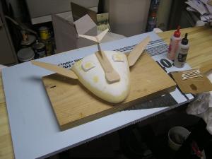
Now attach the tail wing and vertical support as shown in the picture. Round the front edges and add the 1/32” accent piece to the center of the tail piece. Add 2 generous epoxy fillets between the wing and vertical support.
Now the center piece can be assembled, sanded, and mounted. Use Template E and cut out 2 – ¼” balsa pieces. These should be laminated together. You will need to sand the shape as well as the contour it to the shell. This can now be mounted to the center of the shell. Once the center piece is attached to the shell the rear vertical wing can be attached.
The 2 vents (Template G) can be made from balsa or vacuum formed. I chose to vacuum form these to keep the weight down as much as possible. The next step is to trim and fit each vent to the top of the shell. Again take your time, this will be a little tedious.
Finally, mount the square accents to the shell.
Nose Weight:
I determined through a number of test flights nose weight was critical. I used two yellow engine tubes and filled them each with 2 ounces of weight. These are then slid into the front of the 2 non-engine tubes in the tubes assembly. I taped these as far forward as possible.
Engine Cone Assembly:
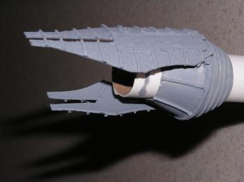
I have to admit I struggled with making the engine cones. I first attempted to vacuum form these without success, and then attempted to make them out of balsa with even worse results. Primarily, because I needed a lathe (which I now have on the Christmas list) or something better than my hand drill. I finally decided to make them out of paper card stock and balsa.
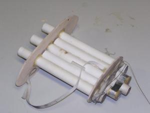
I use the shroud calculator to get the dimensions of the cones I needed. I cut these out of thick card stock and formed 6 cones. Next, I cut out 3 balsa circles - 1.25” in diameter and drilled them out so a BT20 tube would slid through tightly. I mounted the cones to each of the balsa centering rings with a small section of BT20 tube locating the cones and the balsa ring. The centering rings should over hang the cones slightly. Now the big question, how to get the support ribs on to the cone assembly. I chose to use .030” diameter Dacron cord. As you can see from the pictures I cut sections and mounted these to each cone. I covered each cord and cone with CA to add rigidity. After allowing this to dry I sanded the diameter of the balsa centering ring down to the cord diameter and coated the balsa edge with CA. If you look closely at these they are not prefect, but it is a spaceship, things get bent and beat up in use so these turned out pretty good with that thought in mind.
Next are the engine extensions, I created templates (H and I) for these and cut these out of BT50 tube. Then I added the cord used above to create the support ribs shown. When these were done I covered the entire assembly with CA.
Now mount the engine extension to the cones assemblies using CA to tack them and epoxy to add additional strength.
Paint and Finishing
I painted the shell assembly, main body tube, and engine cones separately.
Shell Assembly:
I sprayed 2 or 3 coats on the entire shell assembly with Krylon White Primer. After lightly sanding the primer, I sprayed white gloss (Model Master Acryl 4696). Next, I masked and sprayed gray (Testors Acryl 921535). Next came red (Guards Red), I masked and painted with (Model Master Acryl 4632). The final color was Gloss Black (Model Master Acryl 4695). After black, I added decals for the number and other special symbols. Finally, I added 3 costs of Krylon Crystal Clear Gloss.
Main body tube:
Just as the shell assembly I first applied 2 or 3 coats of Krylon White Primer. Next, came the final coats of gray (Testors Acryl 921535). Finally, I added 3 costs of Krylon Crystal Clear Gloss.
Engine Cone Assemblies:
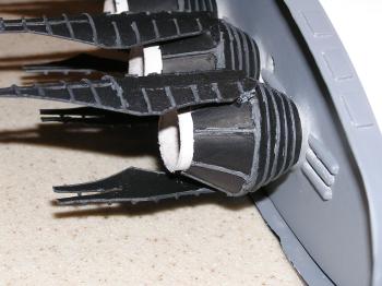
I started by painting the engine cone assemblies with 2 coats of gray (Testors Acryl 921535). Next, I hand painted flat black (Model Master Acryl 4768) between all the support ribs (see attached picture). Next, I sprayed a diluted flat black on to the cone assemblies to give them a weather/used appearance.
Decals:
I printed the decals on Experts-Choice clear water slide decal material. I cut them out and applied them as the pictures shows.
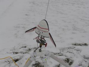
Flight Prep:
Flight Prep was pretty easy. Remove the engine cones. Insert each engine until .12” - .25” is sticking out the engine tube. Tape each engine in place using Mylar tape. Now, fill the engine tubes with wading. Fold the parachute loosely and lay on top of the tube assembly. Next slide the tube assembly in the shell assembly and you are ready to go. You may need to slide the rod through prior to taking it to the launch pad. It is a little hard to slide the rod through with the rod in the vertical position.
Flights:
I made 8 test flights with the prototype version with varying levels of success. Once I was satisfied with the flights I began building the final version.
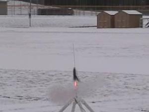
The final 3 flights occurred with the final version of the rocket. I was able to video the last 2 of these flights. I attempted to video all 3 however, had a problem with my camera on the first one. The first flight of the final model occurred in early November. After my flight in September I added a little bit more nose weight to overcome the barrel rolls or cork screws that occurred previously. The flight was nice and straight with good altitude and successfully recovery. The rocket landed in the middle of the field without damage.
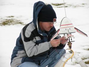
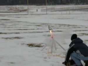
The next flight occurred in early December and it was a nice Wisconsin winter morning; 7 degrees with about 4 inches of fresh snow. The wind was fairly calm maybe 5 mph. This was a reasonably good flight with a couple of twists under boost, the parachute opened nicely. The rocket landed in the middle of the road and suffered some damage to the paint and the top wing broke. I repaired the wing for the third and final flight.
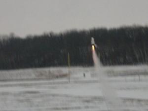
The final flight day arrived and it was raining after being 7 degrees the week before it was now 40 and raining. I found a slight break in the rain so I hurried to the field to make my final launch. It was a little windy (maybe 10-12 mph), but I needed to make my final flight. I angled the rod into the wind to ensure the rocket would land in the field. The rocket boost nice and straight with good altitude; things were looking good until no parachute!!!!!!!!!
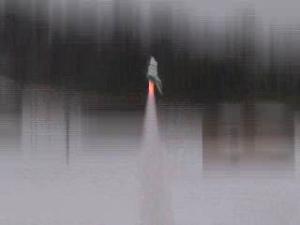
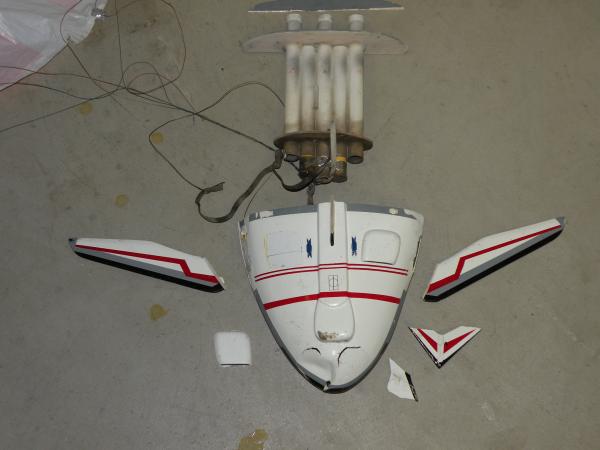
After making 11 flights and 5 of them without any recovery issues; this one was painful. The rocket lawndart'd in the center of a walkway destroying it. I am not sure what happened, the only thing I can think of is I may have wrapped the shock cord up in the tube assemble in such a manner it prevented them from separating or there was something wrong with the ejection charges.
Check out the video – It is painful to watch for me, but my son enjoys it every time he watches it. I plan to re-build and fly it again!
Summary:
Summary (Pro's & Con's)
Pro's
I was very pleased with the overall finish of the rocket, but the engine cones were my favorite. I struggled figuring out the best way to make these and was very pleased with the final results.
Con's
Based on the lack of deployment on the last flight – I am feeling like I might need a pre-flight check list for future flights.
Thanks EMRR - this was a great project. I enjoyed the flight challenges as well as the design and construction challenge. I am looking forward to 2009's spaceship challenge.
 |
 |