Scratch Flaming Mayhem Original Design / Scratch Built
Scratch - Flaming Mayhem {Scratch}
Contributed by Tim Burger
Brief:
A 4-inch upscale of the venerable Alpha.
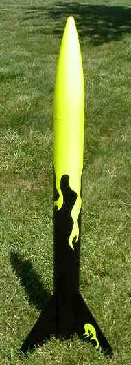 |
| “Flaming Mayhem’s Revenge!” |
During 2002, the local NAR chapter had broken into High Power Rocketry. Some of the core members of the group already had quite a lot of expertise, and the necessary ground support equipment to handle the bigger rockets. Then one of the members was able to get us access to a field that was large enough to handle level 1 and 2 motors and the action began. Several of the club members began planning a level one certification rocket, including me. I tinkered around with several designs, investigated getting a kit, etc, and finally settled on what really is an upscale of the Estes Alpha. Four of my fellow club members certified level one on the same day, but unfortunately I wasn’t quite ready yet, so my level one attempt had to wait another month or two. This really is a lot of fun and for all the same reasons that designing a competition rocket is such a thrill (especially when you win an event.)
Construction:
The design was initially done in Rocksim 5. The components are mostly off-the-shelf parts found in the data base — LOC paper tubes and nose cone, etc. I tinkered with several ideas and designs, but eventually settled on this one since it is so well known and therefore understood at the RCO/LCO table, and the parts are readily available. Also, the simple design helps ensure success - no strange deployment problems or unexpected stability issues. The idea here is to get level one certification, but learn a little something along the way while at the same time employing the skills I’ve gained from the years in the hobby.
With the design in hand, I began “kitting” up. The tubes for the original rocket (lost on the third flight, alas) were purchased from Rocky Mountain Rocketry, along with the nose cone, centering rings, and shock-cord. The Aero Pack retainer was purchased from Aero Pack directly, and the ’chute was custom made by my wife. The fin stock came from the local hobby store, and the remaining hardware, eye-bolts, quick links, etc. were purchase from the local “rocket support store” (non-rocketeers call it the “hardware store.”) The tubes and nose cone for the second one were purchased from Magnum, since RMR had stopped running the Internet/mail order part of their business by then.
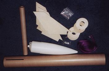 |
| The “kit.” |
The three sheets of 3/16-inch birch aircraft ply were tack glued together, the plan marked out on the top sheet, and cut out on the band saw. The edges were then sanded smooth and uniform with the belt sander. The fins were then popped apart, and sanded to a nice as-even-as-I-can-make-them airfoil with the belt sander. They were then sanded by hand with 220 grit paper to get them smooth enough for assembly. The fin slots were cut in the body tube with a good sharp X-acto knife and a metal straight edge. The motor mount assembly was test fit together and slipped into the tube for support during this operation, then all the parts were assembled to test the fit before mixing epoxy. The motor mount was made by gluing the rings on at the correct place: the lower rings located to match the fin tabs, the top plugged and sides drilled to form a baffle with the upper rings, and the shock-cord mount installed.
At this point, the location of the rings were marked on the outside exactly so that the lug screws would be driven into the wood of the rings for a good firm mount. The mount was glued into the airframe using 30-minute epoxy. A bead was run around the inside of the airframe at the approximate location of the final position of the top ring. A ring of epoxy was also run around the edges on the top of the middle rings. The parts were then fit together with a final ring of epoxy placed in the airframe during assembly at the approximate position of the lower ring. The airframe was then spun rapidly a few times to force the epoxy on the middle rings into the joint. This was allowed to set up well, then the fins were added, one by one, allowing the epoxy to cure before moving on. Fillets were then added to the fin joints and the bottom ring, also using 30-minute epoxy. Holes were drilled at the marks for the rail buttons, hitting the wood nicely. Three small holes are also drilled in the aft centering ring between the fin tabs for pressure relief inside the airframe.
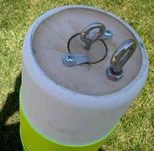 |
| Nose assembly; note the flange left when the conical aft section was removed. The big ring is for the shock cord; the small one is only a handle for the weight plug. |
The original rocket simply used the plastic loop molded into the base of the nose to connect it to the shock cord. Since I had planned to install something a little more substantial, and a removable nose weight for flying with bigger motors, I went ahead and installed the planned upgrade in the new rocket. The conical portion of the nose was carefully removed using the band saw, leaving some of the round edge to form a lip to make the new base more secure. A 3/16-inch hole was drilled into the base plate and a stainless steel eye-bolt was installed for shock cord attachment with a stainless nylon insert nut to keep it there. The base was then glued into the nose using “Super RC Z 56” glue. A 1-1/4 inch hole was drilled into the center, and a 29mm tube that reaches to the front was glued in. This tube is used to hold a hardwood plug, the front of which can be used to hold a stack of washers for ballast. More washers equals more weight for more motor.
Finishing:
My level one certification flight happened before I was able to get a good finish put on. I did eventually paint it, though. Since the fins are ply, I didn’t use any sanding sealer, I just went directly to the primer stage. A good layer of Rustoleum Clean White primer was applied after filling the spirals with Elmer’s Fill ’N’ Finish and sanding everything with 220 grit paper. After the primer cured for a couple of days, it was sanded until the components were peaking through; this is done to fill the wood grain, and fix any fingerprints, etc. Another coat of primer, and another sanding, but this time using 400 grit paper, and only until good and smooth. I find that the primer takes on a sheen when it’s right. After tacking off the dust, a finish coat of Rustoleum’ day-glow yellow was applied. This was masked off in a garish flame pattern, and the lower half hit with Rustoleum Flat Black. I also made an attempt at an orange highlight, which fortunately escaped the camera, but before I was able to try again the rocket was lost at the December Mo/Kan launch. This brings us to the current effort, the “Revenge,” which is pictured in this article. It was finished in much the same way as the original “Mayhem,” and has a final coat of Rustoleum Clear.
Flight:
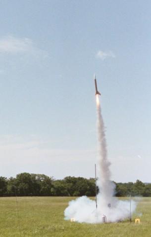 |
| The unfinished “Flaming Mayhem” goes for the certification flight. |
The first flight was on an Aerotech H128-S, the hardware was borrowed from Jerome and the motor was originally Dan’s, who purchased it but was not going to be able to use it so he let me burn it. The motor was assembled under the supervision of Jerome and Nick, and the rocket checked by them before heading out to the pad. The new parachute wasn’t complete yet, so I used a harness and three nylon 24-inch ’chutes from Estes. After the expected amount of nervousness, the countdown finally commenced, and it left the rail on a column of smoke. The delay was pretty close to optimum, and all three ’chutes opened, but didn’t spread out as they should. Even so, the drift was more than expected, and it landed in the next field over on rock hard ground. My friend Bill went with me to collect it, and all looked well until we picked it up and found one of the fins had lost about an inch off of the tip — apparently happened to hit it just right on landing.
I had a few moments of anxiety, thinking that maybe I wouldn’t cert, since it was damaged, but Bill said it looked like cosmetic damage to him. Nick and Jerome both confirmed that, since we could take it right out to the pad and fly it again — that small piece being inconsequential to the stability, etc. After some very kind comments, the paper work was signed off. Whew! My many thanks to everyone who helped me with the certification flight!
It was flown again on a Pro-38 two grain (H153-6) at one of the Argonia launches. When the LCO made the announcement he got a kick out of the name and chuckled all through the countdown. It lit instantly as Pro-38 motors do, and flew quite nicely. That final fateful flight was made at Mo/Kan later in the year on another of the same type motor. The thing simply floated off; I thought I had a good track on it, but it was nowhere to be found even after a good deal of searching. Guess the rocket gods are keen on extra-large Alphas!
The new one has flown on a Pro-38, three grain motor (I205-8), and nearly floated off too. Maybe a little less ’chute, next time!
Related Products
 |
 |