Scratch Interstellar Cruise Liner Original Design / Scratch Built
Scratch - Interstellar Cruise Liner {Scratch}
Contributed by Les Bradshaw
| Manufacturer: | Scratch |
 Brief:
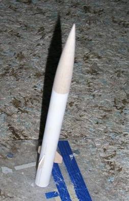
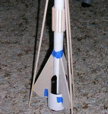
The Intersteller Cruise Liner consists of three segments. At the top, furthest away from the engines, is the cabin
for the passengers with a set of canard fins. Next is the cargo section and finally the hyper-atomic engines. The liner
has the ability to land on a planets surface with it telescoping legs (similar to those golden years of rockets from
the 1950's).
The rocket is over 4' tall and flies on 24mm motors. It uses a combination of tube fin, ring fin, and standard balsa fins.
Construction:
This design and build is for the 2008 EMRR Challenge #6 to use a software program to design a rocket and then build
and fly the design. This is my first real attempt to design a rocket using RockSim. Some issues I ran into may be more
my lack of experience than a shortcoming in the RockSim program.
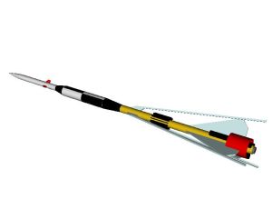
I did not want to do a simple 3FNC design, although for a first attempt at RockSim that may have been a better choice. I wanted something more with the '50s style of sci-fi rockets. While I don't think the rocket came out quite retro style, it is not a 3FNC.
One goal I had was I wanted a combination of fins. I had some 2.84" body tube left over from another project that I wanted to use as a ring fin, but I did not want to use balsa pods to support this ring--I wanted to use tube fins as the ring fin support. I started looking at different size tubes to select a body tube with tube fins that would match the inside diameter of the ring fin. I finally decided on the Semroc LT-115 size with BT-30 tube fins. I was also going to have conventional fins that would intersect with the ring fin that would also end up being the support for the landing legs. A final touch were the radiator fins on the engine compartment to help remove heat and protect the cargo section.
 The cargo compartment I made larger in diameter than the engine tube and the passenger section
reduced down again.
The cargo compartment I made larger in diameter than the engine tube and the passenger section
reduced down again.
My RockSim adventure, and all RockSim designs, start at the nose cone. I added the passenger tube, the transition, the cargo tube, the next transition, and finally the engine tube. When selecting the transition parts, it always assumes the small end is to the front and the larger size is to the rear. You can easily change the properties to reverse the transition, but make sure you remember or write down all the parameters.
Adding the tube fins was easy, but I wanted the tubes beveled. I could not find a way to perform this, so I used the average length for the simulation.
I then added the ring fin. RockSim requires pods to support the ring fin, but I was using the tube fins. I set the pod data to only one cardboard 0.0001" thick pod so it would not affect the design.
 The next step was to add the main
fins. I used the free form plan points to develop the fins. I initially had some problems with this and had to retry a
couple of times, but I finally got it. Now, one advantage and disadvantage of RockSim is it is not a true, 3D modeling
tool so it will not flag any issues with parts interfering with each other. For me it was an advantage as I wanted the
main fin to intersect with the ring fin and I did not have to worry about about trying to include the slot in my fin
plan. On the other hand, if you have a design problem where two items interfere that you did not plan, RockSim will not
warn you.
The next step was to add the main
fins. I used the free form plan points to develop the fins. I initially had some problems with this and had to retry a
couple of times, but I finally got it. Now, one advantage and disadvantage of RockSim is it is not a true, 3D modeling
tool so it will not flag any issues with parts interfering with each other. For me it was an advantage as I wanted the
main fin to intersect with the ring fin and I did not have to worry about about trying to include the slot in my fin
plan. On the other hand, if you have a design problem where two items interfere that you did not plan, RockSim will not
warn you.
I included a second set of fins with the plan for a dowel between the fins. I don't think RockSim could handle the dowel, so I created a weird fin that "combined" the forward fin and the dowel. I specified this fin to be made from fir with a rounded cross section.
I added the motor mount, centering ring, engine hook and block, launch lug, screw eye, and parachutes (as I planned to use an 18" for the engine compartment and a 12" for the cargo/passenger sections).
I initially was going to use small tubes for the radiator section, but RockSim indicated it would be unstable. Actually, at this point RockSim did something strange. I would "fly" it one time and it would be stable and another time it would be unstable. Part of this I discovered was due to the simulation mode--basically, how much wind and how variable the wind would be. You also can set the launch rod length. RockSim indicated I needed almost 4' of launch rod. The default appears to be 3'. I decided during the build to change to 1/4" lug since I have a 6' rod that size. All of my 1/8" and 3/16" rods are only 3' long. A few other things I learned about RockSim is you can specify using either the Barrowman, RockSim, or cardboard cutout to determine stability. You can also use either the nose cone diameter or the maximum frontal diameter for the static margin. I think between the stability calculation method, the static margin basis, and the weather/launch rod is what caused the stable/unstable results.
I did extend the passenger tube some. I finally decided to change from the tube radiators to a balsa fin. RockSim only allows a maximum of 8 fins (I wanted 12), so I set up 3 sets of 4 fins and used the Radial Position to offset them. The straight balsa radiators also helped with the stability issues I had.
Finally, I added the canards because now RockSim indicated the design was overstable.
So now it is time to build--or at least order all the parts.
The final part list consisted of the following:
- BC-944 nose cone
- BR-11518 transition
- BR-918 transition
- BT-30B body tube (for the tube fins)
- LT-115220 body tube (for the engine section)
- LT-27580 body tube (ring fin)
- ST-1890 body tube (for the cargo compartment)
- ST-9180 body tube (for the passenger section and the 24mm engine)
- CR-9115 #9 to #115 centering ring
- EH-38 long engine hook
- 1/4" dowels (the landing legs)
- 3/16" balsa - fins
- 3/32" balsa - canards
- 3/32" X 1/4" balsa - radiators
- 18" parachute
- 12" parachute
- 1/4" elastic cord
- 1/8" elastic cord
I ordered all the parts except the dowels, fin stock, parachutes, and elastic cord from Semroc. I placed the order on Saturday and the box was on my doorstep on Wednesday. The parachutes I had on hand and the elastic cord came from my stock from Wal-Mart.
The very first thing I did, was to check that my concept for the tube fins to be the support pods for the ring fin would work. I dry fit them together and it all slid together nicely.
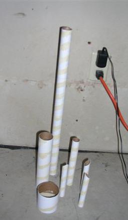 I cut my tubes to length and filled the small spirals (I probably could have
skipped this step as the spirals were small). As with a typical rocket, I built the motor mount first. I made a slot in
the tube, put the hook in, glued the coupler over the top, and the engine block into the tube.
I cut my tubes to length and filled the small spirals (I probably could have
skipped this step as the spirals were small). As with a typical rocket, I built the motor mount first. I made a slot in
the tube, put the hook in, glued the coupler over the top, and the engine block into the tube.
I transfered my fin designs to card stock and cut them from the balsa. I joined the dowel and balsa fins together using a straight edge. Since the dowel was 1/4" and the balsa was only 3/16", I made some shims from scrap card stock and placed it under the fin material. This allowed the dowel to be centered on the fin.
I needed to mark the tubes--I had 12 radiators, 3 tube fins, and 3 dowel/fin units. Knowing the diameter of the tubes, I used a drawing program to lay out a marking guide. Let's see, the circumference of a circle is 2 * pi * r. The diameter of the tube is 1.22" so 1.22 * 2 * pi = the wrong answer. My first layouts looked huge! What did I do wrong? Wait...hey, there is a difference between radius and diameter. (Duh...rocket scientist at work?) Well, at least that was a simple one to fix.
While the main fin/dowel units were drying, I glued the canard to the passenger compartment and the radiators to the engine compartment.
I cut the tube fins to size and beveled them. The bevel used the same pointy approach used by the Pemperton Kraken. I used 1/4" masking tape to mask off the portions of these tubes that would need to be glued and pre-painted them. I knew they would be a pain to paint once assembled.
When the dowel/fin units were dry, I figured out where I needed to slot the fins for the ring tube and used an X-Acto to cut the slots. Then I dry fit everything together again (with the help from masking tape). While it was together, I marked on the ring tube where it would need to be glued. Again, I masked the glue area and pre-painted.
 I glued and filleted the fins onto the engine tube. I masked the glue areas on the tube for
the tube fins and on the balsa fins for the ring fin, and painted the engine compartment. Once dry, I removed all the
masking and finally glued on the tube fins, ring fin, and launch lug. Then I finally glued the motor mount in, lining
the hook up with the launch lug.
I glued and filleted the fins onto the engine tube. I masked the glue areas on the tube for
the tube fins and on the balsa fins for the ring fin, and painted the engine compartment. Once dry, I removed all the
masking and finally glued on the tube fins, ring fin, and launch lug. Then I finally glued the motor mount in, lining
the hook up with the launch lug.
I also painted the cargo and passenger compartments.
I used the Estes tri-fold approach to attach nearly 3' of 1/4" wide elastic for the engine section and about 2' of 1/8" elastic to the screw eye I installed in the transition between the engine compartment and the cargo compartment.
Finishing:
After the rocket was built, I checked out the real rocket against the RockSim specs. My real rocket was heavier by
about 0.7 ounces. My first thought was this was due to the glue, paint, and possibly items (like the elastic cord) that
I had missed in the design. Then I checked the center of gravity. It was much higher in the real rocket than what
RockSim predicted. I went back to the computer and created a mass object equivalent to the 0.7 ounce and moved its
position until the center of gravity match the real rocket. I simulated a flight, but since the rocket was already
stable, moving the cg forward only made it better (possibly overstable).
One concern I did have was whether the dowels would survive hitting the ground. I thought of reinforcing them, but I was concerned about how heavy the rocket was getting. Also, I was running out of time! RockSim indicated the rocket would only go 214' and the rocket would be traveling at over 30 fps when the chute ejected (part of the reason for the long elastic cord).
Flight:
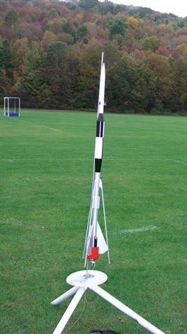
Well, time was running out to try to fly this beast. I loaded up the car and went to the school yard. Weather was
poor with on and off rain and drizzle. I get there, and the field is in use. I went back later. The weather was still
poor, but I only had 2 days left to meet the challenge deadline. I set up the pad with the 6' long 1/4" rod and
loaded a D12-3 engine. A few photos and 3-2-1 launch. Well, the rocket went "straight" up, but an interesting
thing happened. It did not weathercock, however, I did see it drift sideways due to the wind.
 Recovery:
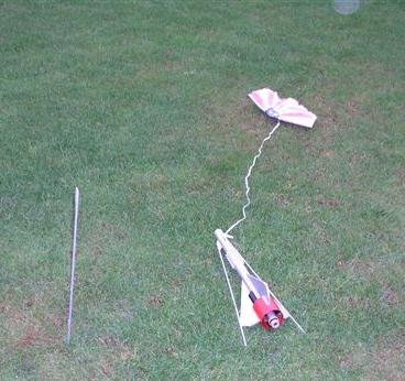
To me it looked like the chute came out just after apogee but not after falling and picking up speed to the 30 fps.
In fact, initially the cargo/passenger section was floating down sideways since the 12" chute did not want to pop
open. The rocket drifted a bit, and then landed. It stuck the landing, sort of. The one dowel was stuck in the ground
with the rocket laying on its side next to it. I knew I should have reinforced that joint! Otherwise, the rocket did
fine. I think I would change the 18" parachute for a 24" to slow the landing.
Summary:
Well, it was an interesting exercise really using RockSim for the first time. To me it looks like for a standard 3FNC
rocket it is easy to use. If you want to make exotic or fantasy type rockets, you will need to play many games and may
even need to question the results. I'm not even sure it could handle some of the Shrox rockets, the Fliskits ACME
Spitfire, the Odyssey, or others of that type. The Apogee website does have many tips in the "e-zine" section
though. Some of the tips will allow RockSim to properly simulate the rocket, but it then can't properly display what
the rocket looks like. There are also tips that can be found in some of the various forum sites.
In the long run, I am not happy with the paint job. It looks too much like I just joined 2 different rockets. I think I would have been better off keeping the passenger and cargo compartments silver instead of white. But I was happy with the tube fin/ring fin/balsa fin combination.
 |
 |