Scratch ISS Pluto Original Design / Scratch Built
Scratch - ISS Pluto {Scratch}
Contributed by Chan Stevens
| Manufacturer: | Scratch |
The ISS Pluto
Click on Pics to
Enlarge 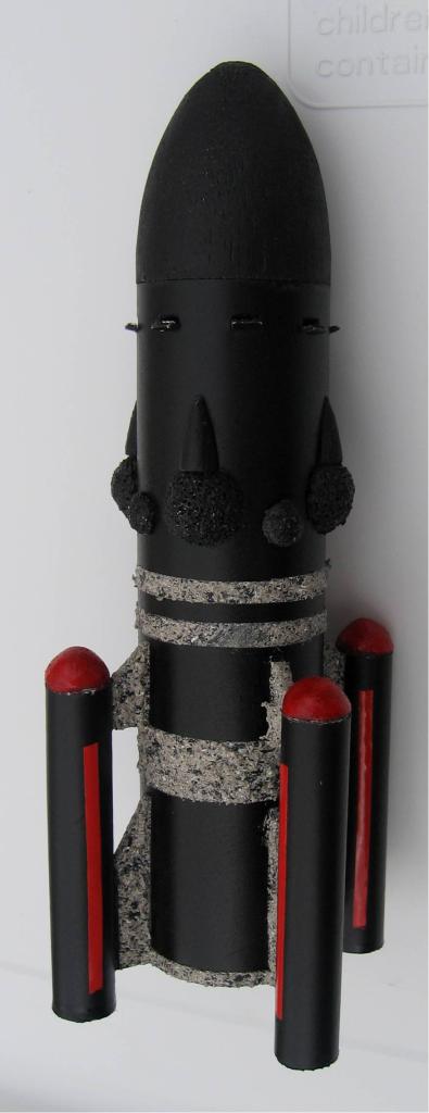
Well, Pluto may no longer be a planet, but the name will live on forever as the first Interplanetary Space Shuttle. The final version is not scheduled for completion until 2012 (and has not yet received funding), but a reasonable prototype can be built from relatively inexpensive materials and flown on the much more common model rocketry hobby motors.
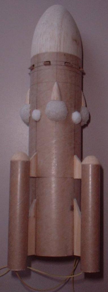
There are a few custom-turned parts for this model, which I ordered from Balsa Machining Service. The main nose cone is designed to fit a BT-60, so is 1.64 OD and a length of 1.845 inches, using an elliptical shape. The pod cones are sized for BT-5, so 0.544 OD and a length of about 0.5. I went with parabolic, though had to sand down to shape (more on that later). I also picked up a pair of cones for modeling the bays on the side of the main body tube (parabolic, 0.3 OD x 0.51 length).
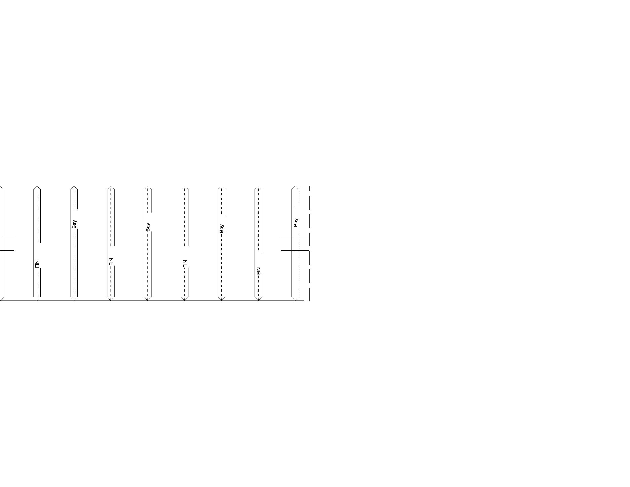
Body tube lengths and fin templates can be pulled from the attached Rocksim file. The fins really need to be made from basswood, not balsa, as they will be subjected to plenty of stress both in flight and in recovery.
You’ll also need Kevlar, a launch lug, some nose weight, (4) 6" chutes, and several Styrofoam balls (which I picked up from the nearby national chain crafts store).
Start out by cutting out four sets of forward and aft fins from 3/32 basswood. Make sure the grain is parallel to the leading edge. Next, sand the BT-60 tube and BT-5’s lightly to remove any glassine shine. This will dramatically improve the strength of the bond.
Mark the body tube for four fin lines and the four bays using the template attached.
Next, you’ll need to mark lines around the BT-60 at 2.25" for the aft edge of the forward fins, at 5.25" for the tip of the bays, then a pair of lines at 5.625 and 5.75 for the vents.
The aft fins are bonded to the BT-60 flush with the bottom of the BT-60. The forward fins are bonded with the aft edge positioned on the 2.25" line. Apply multiple, generous wood glue fillets and allow plenty of time to dry. Next tack on the (4) BT-5 motor tubes, with the forward end aligned with the tip edge of the forward fins. You won’t have much room to work, but fillets are needed here as well. I used a Q-tip and toothpick to apply my fillets.
The bays are a little tricky, but can be reasonably modeled with care. Start by splitting the small nose cones in half vertically and removing the shoulders. Tack each one to the BT-60 with the tips at the 5.25 line. Next, take one of the Styrofoam balls and cut it in half. Sand each half down until it is roughly half an inch diameter. It might take a couple of practice tries, but I found that this really wasn’t too tough when using 120-grit sandpaper. Flatten one end of the circle a bit by pressing it against the base of the split cone, then tack it in place using white glue.
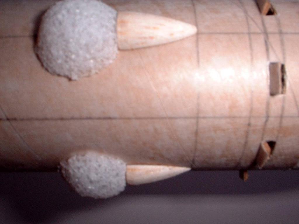
The last detail to form and bond are the four porthole orbs, each formed from Styrofoam using the same technique as the bays, but a bit smaller—roughly 0.25" diameter. These are spaced evenly between and slightly below the bays.
Once the Styrofoam parts have been tacked in place, coat them with a thin application of white glue, brushed on. Once the glue has dried, repeat with one more coat. This really stiffens the foam and makes it much easier to paint.
Next, mark out and cut the vents using the attached pattern (windows), positioned between the 5.625 and 5.75 lines. DO NOT CUT OUT THE BOTTOM—cut only the top and sides, then lightly score the bottom. The pattern sheet is scaled to mark the sides, but is marked slightly taller than the vents should be. Using the tip of a hobby knife or toothpick, push the vents open from the inside. You might need to apply a drop of thin CA if the edges are frayed.
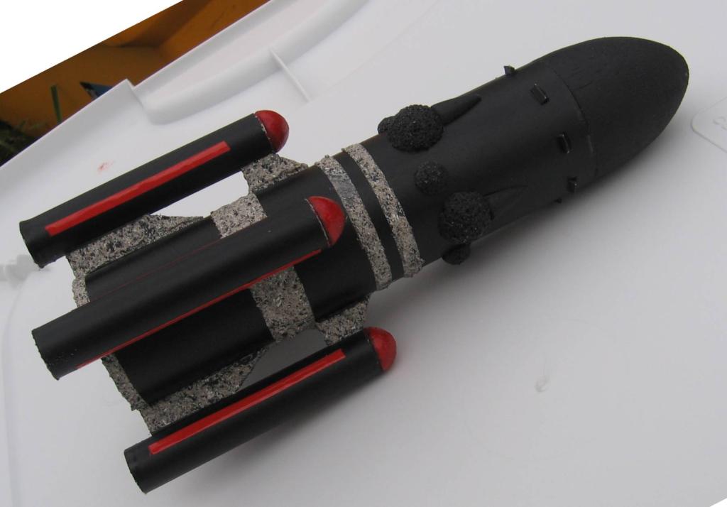
 The main nose cone will need
to be modified quite a bit. First, remove all but 1/8" of the shoulder (so
the vents are not blocked). Next, using your favorite rotary tool, carve out a
large opening from the center of the cone. You’ll need quite a bit of room
for nose weight. For nose weight, I suggest BB’s and epoxy. You’ll
need enough to bring the CG to about 1.1" aft of the end of the BT-60 with
motors loaded. When you have the proper amount of weight loaded, glue the cone
in place to the BT-60.
The main nose cone will need
to be modified quite a bit. First, remove all but 1/8" of the shoulder (so
the vents are not blocked). Next, using your favorite rotary tool, carve out a
large opening from the center of the cone. You’ll need quite a bit of room
for nose weight. For nose weight, I suggest BB’s and epoxy. You’ll
need enough to bring the CG to about 1.1" aft of the end of the BT-60 with
motors loaded. When you have the proper amount of weight loaded, glue the cone
in place to the BT-60.
The four nose cones for the motor tubes need to be sanded down to a much more blunted circle. Try to maintain the 0.544 diameter, but only about 0.25 height above the shoulder. Next, cut a length of about 8" of Kevlar (recommend at least 120-pound), and tie a knot in one end. Poke a hole in the shoulder of the nose cone with a toothpick, and glue the knotted end of the Kevlar inside. Repeat for the other 3 cones.
Attach a 1/8" launch lug somewhere forward of the fins, being careful not to be blocked by one of the vents.
For painting, I recommend two light coats of gray primer. The finish should be a semi-flat black. I used Krylon Satin, which goes on a bit thick but offered just the right gloss. For the accent/trim, I used faux stone paint that looks like gray granite or marble. There should be a band of about 0.25" at the base, 0.5" just aft of the forward fins, and a pair of 0.25" stripes in front of the forward fins. The fins themselves are also painted gray granite.
Finally, the (4) motor tube nose cones get painted orange, and if you’re really daring you can also paint two stripes on each motor tube (orange).
Flight prep is a bit tricky on this, as it’s a 4-motor cluster with very little room for the chute and wadding. I recommend a lariat-loop motor retention—tie a slip knot in the free end of the Kevlar, thread it through the forward end of the tube and out the aft end, and secure the loop around the motor (the motor will need a little tape ring at the nozzle end to serve as a block). Next, insert the motor into the tube, pulling the Kevlar along with it (from the front). Insert roughly ¼ square of recovery wadding or dog barf, then slip in your chute. Repeat for the other 3. Sort through your igniters and make sure you select (4) in excellent condition, as you MUST light all 4 motors for this to be stable. A clip-whip is also highly recommended.
Flight report
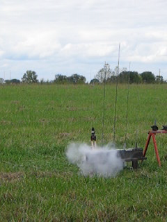
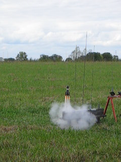
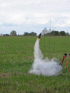
Given the weight and 13mm motor tubes, for the first flight I recommend going with full A10’s. I loaded mine with A10-3’s. Only 3 of the 4 lit, and the rocket never had a chance, flopping over and pranging under thrust. Fortunately, with all the epoxy in the nose, there was no damage. I reloaded with A3-4’s, and fared a bit better—two lit immediately, a third lit just as it started to lift, and the fourth lit just before it left the rod (see still frame photos). Given the slightly asymmetrical thrust, it veered off on an almost horizontal path, ejected way too late, and landed nose first pretty hard, but on soft grass (still undamaged).
 |
 |
 |
| First two lit | #3 lights up | Finally got the fourth |
A third attempt on A10’s proved much better, lighting all 4 and getting a much more vertical flight to about 100 feet. Just for amusement (and to achieve a third motor combination), I tried 1/2A3’s. While all 4 lit, the thrust was barely enough to get it off the rod, peaking at about 25 feet. Even at 2-second delay, the chutes barely came out before it hit the ground.
 |
 |